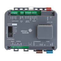
ATC1510 Advanced Terminal Unit Controller
Installation Guide
About This Product
The Advanced Terminal Unit Controller (ATC) runs
custom, freely-programmed applications, and provides
the inputs and outputs required to monitor and control
a wide variety of HVAC/R equipment.
The ATCs operate as BACnet
®
Application Specific
Controllers (B-ASC) and integrate into Johnson
Controls
®
and third-party BACnet systems.
Communication Protocols
You can configure the field bus communication
protocol in the ATC as a standard BACnet MS/TP device
or an N2 protocol device. You can use the Controller
Configuration Tool (CCT) to switch the communication
protocol. Switchable communication protocols provide
a cost-effective upgrade and modernization path for
customers with existing N2 controllers.
Compliance Information
This equipment has been tested and found to comply
with the limits for a Class A digital device pursuant to
Part 15 of the FCC Rules. These limits are designed
to provide reasonable protection against harmful
interference when this equipment is operated
in a commercial environment. This equipment
generates, uses, and can radiate radio frequency
energy and, if not installed and used in accordance
with the instruction manual, may cause harmful
interference to radio communications. Operation
of this equipment in a residential area may cause
harmful interference, in which case the users will
be required to correct the interference at their own
expense.
This Class (A) digital apparatus meets all the
requirements of the Canadian Interference-Causing
Equipment Regulations.
Installation
Observe the following guidelines when installing an
ATC:
• To minimize vibration and shock damage to the
controller, transport the controller in the original
container.
• Verify that all parts shipped with the controller.
• Do not drop the controller or subject it to physical
shock.
Parts Included
• One Advanced Terminal Unit Controller
• One installation instruction guide
• 10 cable ties
• One multi-language warning sheet
Accessories
Table 1: Accessories
Product Code Number Description
LC-IP20 IP20 Terminal Cover Kit
Required Materials and Special Tools
• Three fasteners appropriate for the mounting
surface (M4 screws or #8 screws)
• One 20 cm (8 in.), or longer, piece of 35 mm DIN rail
and the appropriate hardware for DIN rail mount
• Small straight-blade screwdriver to secure the wires
in the terminal blocks
*241014302015—*
24-10143-02015 Rev —
2019-05-20
(barcode for factory use only)
LC-ATC1510-0