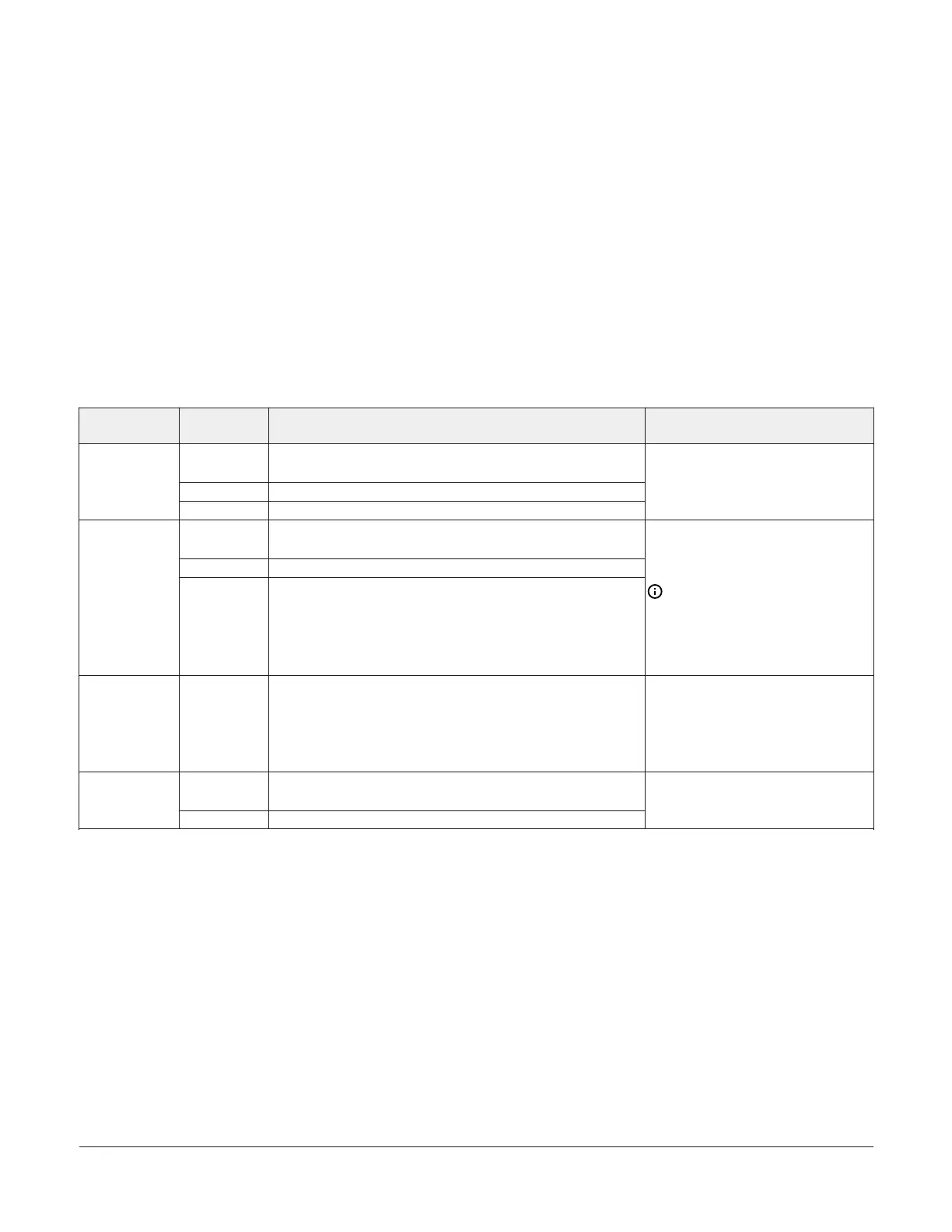
Communications bus and supply power wiring guidelines
Table 4 provides information about the functions, ratings, and requirements for the communication bus and
supply power terminals. The table also provides guidelines for wire sizes, cable types, and cable lengths for wiring
the controller's communication buses and supply power.
In addition to the guidelines in Table 4, observe the following guidelines when you wire an FC or SA bus and the 24
VAC supply power:
• Run all low-voltage wiring and cables separate from high-voltage wiring.
• All FC and SA bus cables, regardless of wire size, should be twisted, insulated, stranded copper wire.
• Using shielded cable is best practice for all FC and SA bus cables.
• Refer to the MS/TP Communications Bus Technical Bulletin (LIT-12011034) for detailed information regarding wire
size and cable length requirements for FC and SA buses.
Table 4: Communications bus and supply power terminal blocks, functions, ratings, requirements, and
cables
Terminal block/
Port label
Terminal
labels
Function, electrical ratings/Requirements
Recommended cable type
1
+
-
FC Bus Communications
COM Signal Reference (Common) for Bus communications
FC BUS
2
SHIELD Isolated terminal (optional shield drain connection)
0.5 mm
2
(22 AWG) stranded, 3-wire
twisted, shielded cable recommended
+
-
SA Bus Communications
COM SA Bus Signal Reference and 15 VDC Common
SA BUS
2
PWR
15 VDC Supply Power for Devices on the SA Bus
(Maximum total current draw for the SA Bus is 210 mA.)
0.5 mm
2
(22 AWG) stranded, 4-wire
(2 twisted-pairs), shielded cable
recommended.
Note: The + and - wire
are one twisted pair, and
the COM and SA PWR are
the second twisted pair of
wires.
SA BUS (Port)
2
SA BUS
RJ-12 6-Position Modular Connector provides:
SA Bus Communications
SA Bus Signal Reference and 15 VDC Common
15 VDC Power for devices on the SA bus and BTCVT or MAP
Gateway
24 AWG 3-pair CAT3 cable <30.5 m
(100 ft)
LINE
240 VAC Power Supply - Line
Supplies 240 VAC (50/60 Hz)
240VAC, 20VA
NEUTRAL 240 VAC Power Supply - Neutral
1.0 mm
2
(18 AWG) 2-wire
1 See Input and Output wiring guidelines to determine wire size and cable lengths for cables other than the recommended cables.
2 The FC bus and SA bus wiring recommendations in this table are for MS/TP Bus communications at 38.4k baud. For more
information, refer to the MS/TP Communications Bus Technical Bulletin (LIT-12011034).
ATC1510 Advanced Terminal Unit Controller Installation Guide8