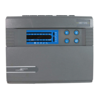
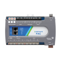
Table 8: Advanced Terminal Unit Controller
Input and Output Capabilities
Binary Input (BI):
Dry Contact Maintained
Pulse Counter/Accumulator Mode (30 Hz)
Dry Contacts; SELV, Limited Power (<15 Watts), Class 2
Universal Input (UI):
User-Configurable, 3 available modes: Voltage Input: 0 VDC to 10 VDC, Resistive
(0 kΩ to 10 kΩ), Dry-contact maintained binary
Same circuit as modules logic circuitry +15 VDC, 100 mA SELV, Limited Power
(<15 Watts), Class 2
OR
0 V to 10 V or 0 kΩ to 10 kΩ or Dry Contact closure; SELV, Limited Power (<15
Watts), Class 2
Configurable Output (CO):
User-Configurable, 2 available modes:
Voltage Output: 0 VDC to 10 VDC, 10 mA; Same circuit as modules logic circuitry
(0 V to 10 V or 4 mA to 20 mA); SELV, Limited Power (<15 Watts), Class 2
Triac Output: 24 VAC, 500 mA (Externally sourced); Isolated circuits; SELV, 24 VAC,
0.5 A resistive; Not-limited power (>15 Watts) Class 2
24 VAC out for actuator power (VAC_P): 24 VAC @ 500mA
Same circuit as modules logic circuitry 24 VAC, SELV; Not-limited power (>15
Watts) Class 2, 0.5 A
5 A Relay Output (5A RO) (K1, K2, K3):
Single-Pole, Single-Throw, Normally Open
240 VAC, 5 A Resistive, 50k cycles
240 VAC, 0.66FLA/4LRA, 50k cycles
Shared common terminal between all 5A ROs
Binary Output Triac (BO):
24 VAC or 240 VAC, 500 mA Resistive
Externally powered
Shared common terminal between all BO Triacs
10 A Relay Output (10A RO) (K8):
Single-Pole, Single-Throw, Normally Open
240 VAC, 10 A Resistive, 100k cycles
For the line-voltage-capable outputs, ensure that they are wired correctly before
applying power.
Input and Output Count 2 BI, 4 UI, 3 CO, 3 RO (5 A), 2 BO, 1 RO (10 A)
Analog Input/Output Resolution
Analog Input: 12-bit resolution
Analog Output: 15-bit resolution
Terminations
Input/Output: Screw terminals
FC Bus: 4-wire pluggable Screw Terminal Block
SA Bus: 4-wire pluggable Screw Terminal Block and RJ-12, 6-pin modular jack
Mounting
Mount the controller using a 35 mm DIN rail, or three screws and the integral
mounting clips on the controller.
Ensure that the controller is mounted so that the side with the outputs/power-
input is "up".
If IP20 covers are not in use, or if local regulations do not allow surface
mounting, the controller must be mounted in or on a panel.
The IP20 covers and cable strain reliefs have been designed to permit surface
mounting in certain countries.
Dimensions (H x W x D)
165 x 130 x 63 mm including terminals and mounting clips
165 x 165 x 63 mm (With IP20 Cover)
Weight 0.6 kg (1 lbs 5 oz)
ATC1510 Advanced Terminal Unit Controller Installation Guide 19
 Loading...
