EDA-2040/ATP-2040 Electric Damper Actuator Installation Technical Bulletin 5
4. After bottoming each screw against the damper
shaft, continue turning the hex key until obtaining
approximately a 30 degree deflection of the
wrench as illustrated in Figure 7 (40 to 65 in·lb).
Repeat for the other hex set screw.
5. Place the actuator onto the coupler in the
desired mounting position 1/8 in. (3.2 mm) from
the mounting surface as shown in Figure 8 so
that the wiring connections are easily accessible.
6. Mark the center of the shoulder washer on the
mounting surface and then remove the actuator
from the coupler.
7. Drill a 5/32 in. (4 mm) hole into the mounting
surface through the mark.
8. Install the actuator onto the coupler so the
shoulder washer is over the hole, insert the
anti-rotation screw and tighten.
9. Connect a 24 VAC power source to the actuator
(cannot manually rotate a flush mounted
EDA-2040), and drive it to the full open and
closed positions to be sure of damper operation.
Proceed to the
Connections
section to continue
installation.
!
CAUTION: Equipment Damage Hazard.
Do not remove anti-rotation
screw and force damper blade
closed using the actuator. This
puts additional stress on the
gear train and could reduce the
life of the actuator.
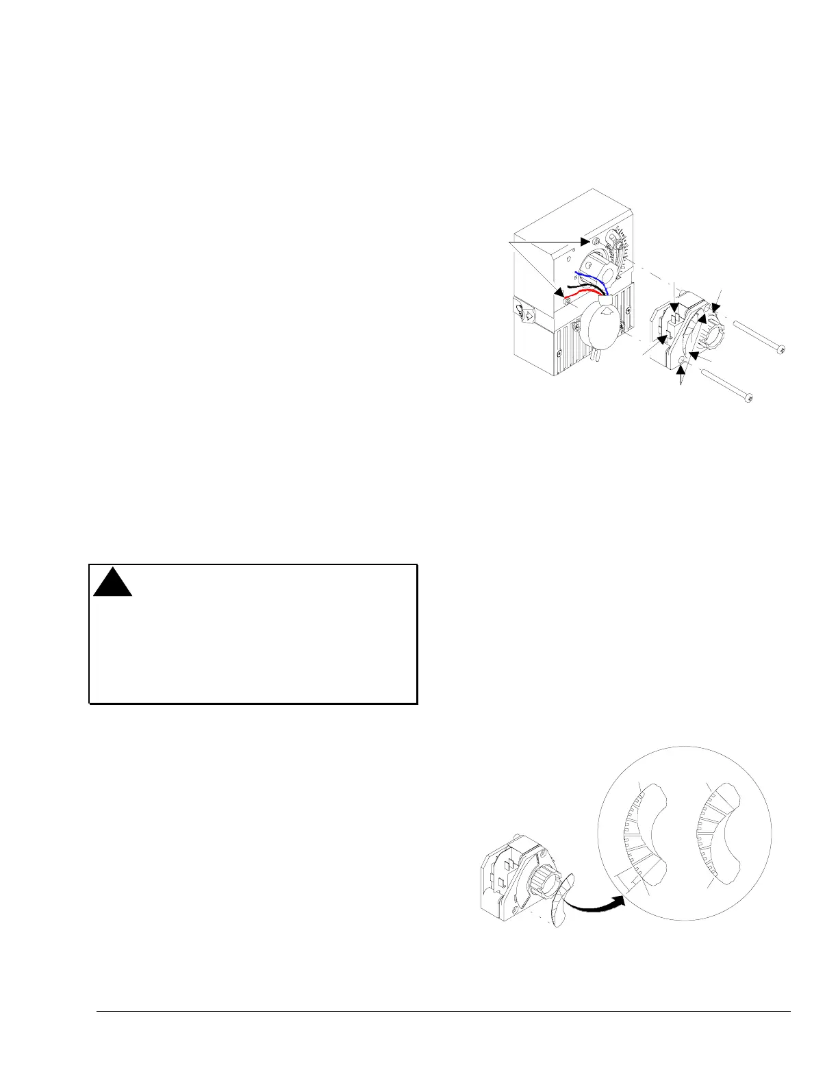
Switch Kit
Note: An EDA-2040 actuator with bosses on the
housing is required for switch mounting.
(See Figure 9.)
Bosses
(
-
)
L
O
O
U
T
G
N
D
I
N
U
P
D
P
T
-
2
0
1
5
Insert
Screws
Switch Kit
Top
Switch
Position
Indicator
Position
Scale
Bottom
Switch
Figure 9: Switch Kit Components
1. Install the standard coupler onto the actuator as
instructed in the
Mounting, Standard
section.
2. Position the switch kit so that the switch kit
coupler fits onto the actuator coupler.
3. Install the two screws to secure the switch kit to
the bosses on the actuator.
4. Verify that the damper is closed.
5. Verify that the position indicator points to the
damper closed position on the scale.
If the position indicator is not pointing to the
damper closed position, lift the scale from the
switch kit, reverse the scale, and install by
inserting its tabs into the recessed slots of the
switch kit. The position scale has two sides as
shown in Figure 10.
CCW
To Close
CW
To Close
15°
5°
Close
Open
Close
Open
Figure 10: Position Scale Installation