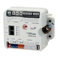
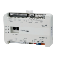
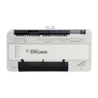
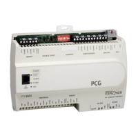
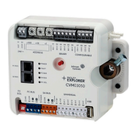
Table 5: Status LEDs and description of LED states
LED label LED color Normal state Descriptions of LED states
FAULT Red Off Steady
2 blinks followed by long pause = Controller powered
on in default state. For more information about this
default state, see .
Blink - 2 Hz = Download or startup in progress, not
ready for normal operation, SA Bus devices offline
(such as netsensors)
Rapid blink = SA Bus communications issue
Off Steady = No faults
On Steady = Device fault or no application loaded
FC BUS Green Blink - 2 Hz
Blink - 2 Hz = Data transmission (normal
communication)
Off Steady = No data transmission (auto baud in
progress)
On Steady = communication lost, waiting to join
communication ring
SA BUS Green Blink - 2 Hz
Blink - 2 Hz = Data transmission (normal
communication)
Off Steady = No data transmission (N/A - auto baud
not supported)
On Steady = Communication lost; waiting to join
communication ring
EOL Amber Off
On Steady = EOL is active
Off Steady = EOL is not active
27F4-CVM VAV Terminal Equipment Controllers Installation Instructions
 Loading...

