2. Place the CVM controller in the proper mounting position on the damper shaft so that the
wiring connections are easily accessible. Make sure the controller base is parallel to the VAV
box (perpendicular to the damper shaft). If needed, use a spacer to offset tipping of the
controller caused by the shaft bushings.
Note: Use the alignment marks to center the captive spacer to ensure sufficient CVM
movement in either direction.
3. Secure the self-drilling No.10 screw through the captive spacer with a power screwdriver and
100mm (4in.) extension socket. Otherwise, use a punch to mark the position of the shoulder
washer, and then drill a hole into the VAV box using a 3.5mm (9/64in.) drill bit. Insert the
mounting screw and tighten against the spacer.
Important: Do not overtighten the screw, or the threads may strip. If mounting to the VAV
box, make sure the screws do not interfere with damper blade movement.
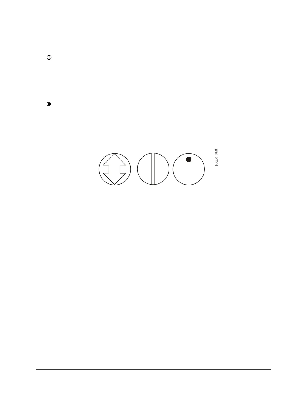
4. Locate the damper position using the typical marking on the end of the damper shaft as
shown in the figure below.
Figure 2: Typical damper end shaft icons
5. Note the direction, clockwise (CW) or counterclockwise (CCW), required to close the damper.
Grasp the damper shaft firmly with pliers, and either manually close the damper for 90° boxes
or manually open the damper for 45° or 60° boxes.
6. Push down and hold the Manual Override button and turn the CVM controller coupler until it
contacts the mechanical end-stop at either the full-closed (90° boxes) or full-open (45° and 60°
boxes) position.
7. If the damper for a 90° box closes CCW, rotate the coupler to the CCW mechanical limit. If the
damper for a 90° box closes CW, rotate the coupler to the CW mechanical limit. The open end-
stop is automatically set for 90° boxes. For 45° and 60° boxes, you must provide hard stops at
both full-closed and full-open damper positions. If you install the CVM controller at the full-
open position, the controller provides the open stop for 45° and 60° boxes. The closed damper
seal provides the full-closed stop.
8. All models are compact in size and are easily installed on VAV boxes. The models have either a
round shaft up to 13 mm in diameter or a 10 mm square shaft. Tighten the square coupler bolt
to the shaft using an 8 mm (5/16 in.) wrench or 10 mm (3/8 in.) 12-point socket. Tighten to 10.5
to 11.5 N·m (95 to 105 lb·in).
9. Loop the pneumatic tubing (supplied by field personnel) to include a trap for condensation.
Attach the needed length of tubing (supplied and installed by field personnel) to the dual port
fitting on the CVM controller and the other ends of the tubing to the pressure transducer in the
VAV box application .
F4-CVM VAV Terminal Equipment Controllers Installation Instructions4