FCP-NA-701, FCP-PA-701
24-11482-00006 Rev. —
7
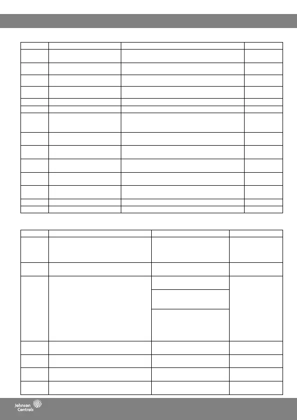
Menu item Description Setting options Default
01 Temperature scale F: Fahrenheit
C: Celsius
F
02 User temperature calibration Temperature with calibration value. Oset: +/- 5.4°F (+/-
3.0°C)
0.0°F (0.0°C)
03 Temperature calibration – remote
sensor
Temperature with calibration value. Oset: +/- 5.4°F (+/-
3.0°C)
0.0°F (0.0°C)
04 Temperature calibration – pipe
sensor
Temperature with calibration value. Oset: +/- 5.4°F (+/-
3.0°C)
0.0°F (0.0°C)
05 Backlight on duration 10 seconds, 30 seconds, always ON 10 seconds
06 Backlight brightness level 20, 40, 60, 80, 100 80
07 Display content 0: ambient temperature + set temperature
1: set temperature only
2: ambient temperature only
0
08 Clock format
(available only on FCP-PA-701)
12: 12 hour
24: 24 hour
12
09 Auto Daylight Savings
(available only on FCP-PA-701)
ON: Auto DST on
OFF: Auto DST o
ON
10 Programming mode
(available only on FCP-PA-701)
ON: programmable
OFF: manual
OFF
11 Periods per day
(available only on FCP-PA-701)
1, 2, 3, 4, 5, 6 2
12 Use default temperatures after
mode change
ON: uses default temperatures
OFF: uses last temperature for each mode
ON
13 Default heat mode set temperature 60°F (15.5°C) - Max Heat Set Temp 70°F (21°C)
14 Default cool mode set temperature Min Cool Set Temp - 80°F (27°C) 74°F (23.5°C)
Table 5: User preference settings
Menu item Description Setting options Default
21 System type 2FCU: 2-pipe fan coil unit
4FCU: 4-pipe fan coil unit
HP: heat pump
H-C: conventional (furnace elect)
4FCU
22 2-pipe FCU with aux heat available
(available only if system type = 2FCU)
Yes
No
No
23 Available modes 2FCU without aux heat:
04: heat and cool without auto
2FCU without aux: 04
2FCU with aux: 03
4FCU, HP, or H-C: 03
2FCU with aux heat:
03: heat and cool with auto
04: heat and cool without auto
4FCU, HP, or H-C:
01: heat only
02: cool only
03: heat and cool with auto
04 : heat and cool without auto
24 HP valve type
(unavailable if system type = HP)
B: B valve
O: O valve
B
25 Remote sensor location 0: in room
1: in duct
0
26 Remote sensor type 0: type II
1: type III
0
27 Pipe sensor type 0: type II
1: type III
0
Table 6: System conguration settings (part 1 of 2)

 Loading...