EasyManua.ls Logo

Johnson Controls T25 - User Manual

Johnson Controls T25
5 pages
Print Icon
To Next Page IconTo Next Page
Loading...
Installation Instructions T25
Issue Date 02/15/02
© 2002 Johnson Controls, Inc.
1
Part No. 24-9716-5, Rev. A www.johnsoncontrols.com
T25 Two-Stage Room Thermostat
Application Requirements
T25 thermostats are for line- or low-voltage service
requiring accurate control of two operating functions.
There are two stages of control for heating and
cooling with automatic changeover on three- and
four-pipe fan coil installations and similar
applications. Typical uses are for compressor
controls, relays, valves, fan coils, and other
applications where low differentials and accurate
sensing are required.
Installation
IMPORTANT: The T25 Series Thermostats are
intended to control equipment under normal
operating conditions. Where failure or malfunction
of the T25 Thermostats could lead to an abnormal
operating condition that could cause personal
injury or damage to the equipment or other
property, other devices (limit or safety controls) or
systems (alarm or supervisory systems) intended
to warn of, or protect against, failure or malfunction
of the T25 Thermostats must be incorporated into
and maintained as part of the control system.
Parts Included
1 thermostat
1 Allen wrench
2 machine screws
Dimensions
Refer to Figure 1 for detailed dimensions of the T25
Two-Stage room Thermostat.
Mounting
Location Considerations
Mount the thermostat about 4 to 5 ft. (1.2 to 1.5 m)
above the floor on an interior wall, where it can sense
the average room temperature. It is designed for vertical
mounting and will produce the lowest operating
differentials when installed in this position.
Do not mount the thermostat where it may react to heat
or cold from water pipes, windows, doors, lamps,
sunlight, or other heat or cold sources.
On unit heater applications, place the thermostat below
and behind the heater in the path of air entering the unit,
not in the path of discharge air.
2.78
(71)
1.13
(29)
5.22
(133)
0.63
(16)
Diameter
1.06
(27)
1.94
(49)
1.88
(48)
0.41
(10)
Two Threaded
Studs
3.28
(83)
0.63
(16)
Two Mounting Holes
0.28
(7.1)
0.15
(3.8)
x
2.84
(72)
1.44
(37)
Figure 1: T25A Dimensions, in. (mm)

Other manuals for Johnson Controls T25

Question and Answer IconNeed help?

Do you have a question about the Johnson Controls T25 and is the answer not in the manual?

Johnson Controls T25 Specifications

General IconGeneral
BrandJohnson Controls
ModelT25
CategoryThermostat
LanguageEnglish

Summary

Product Overview and Requirements

Application Requirements

Details the intended use and applications for T25 thermostats in HVAC systems.

Thermostat Dimensions

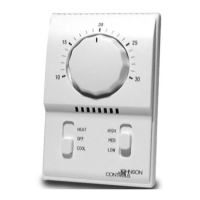
Provides detailed physical dimensions of the T25 Two-Stage Room Thermostat.

Installation and Mounting

Important Installation Safety Warning

Critical safety warning regarding potential injury or damage from thermostat failure.

Mounting Location Considerations

Guidance on selecting an optimal location for thermostat mounting to ensure accurate sensing.

Wall Box Mounting Instructions

Step-by-step guide for mounting the thermostat to an electrical conduit box.

Wall Surface Mounting Instructions

Step-by-step guide for mounting the thermostat directly to an interior wall surface.

Wiring and Control Diagrams

General Wiring Guidelines

Instructions for making wiring connections using copper conductors and safety precautions.

Low-Voltage Wiring Specifications

Specifications for wire gauge and splice methods for low-voltage thermostat applications.

Two-Stage Control Switching Action

Explanation of how the thermostat switches between heating and cooling stages.

Typical Wiring Diagrams

Illustrations of typical wiring configurations for various HVAC system types.

Setup, Adjustments, and Checkout

High Temperature Stop Commissioning

Procedure for setting a maximum temperature limit on the thermostat dial.

Thermostat Calibration

Note that thermostats are factory calibrated and field calibration is not recommended.

Operational Checkout Procedure

Steps to verify correct operation of heating and cooling cycles after installation.

Repairs and Replacement

Instructions to contact Johnson Controls for repairs or replacement of thermostat components.

Technical Specifications

Electrical Ratings Table

Details electrical load ratings for various voltage levels.

Technical Data Summary

Overview of product specifications including output, switches, range, and sensing element.

Terminals and Thermometer

Description of terminal color coding and bimetal thermometer details.

Agency Listings

Information on UL and CSA certifications for the thermostat.

Related product manuals