FIRECLASS Fire detection system Note FC-FI Switches and Jumper Positions
Installation Guide Doc. version 2.0 25
10.5 Note FC-FI Switches and
Jumper Positions
The FC-FI board has many connectors, jumpers and
configuration switches. These are used, for example,
when diagnosing problems and when configuring the
board for additional modules. It is outside the scope of
this installation guide to provide details of these, and the
factory settings will be applicable in most situations.
Where necessary details will be found in other guides,
such as installation leaflets.
10.6 Make Jumper and DIP Switch
Settings
Most jumpers and DIP switches on the GUI, FC-FI board
optional slot cards are already at the required settings as
supplied. For example Debug mode is disabled, Boot
mode is disabled, and so on. The default factory set-
tings are marked by * in the following tables.
Some special operational setting should be
implemented under the specific project.
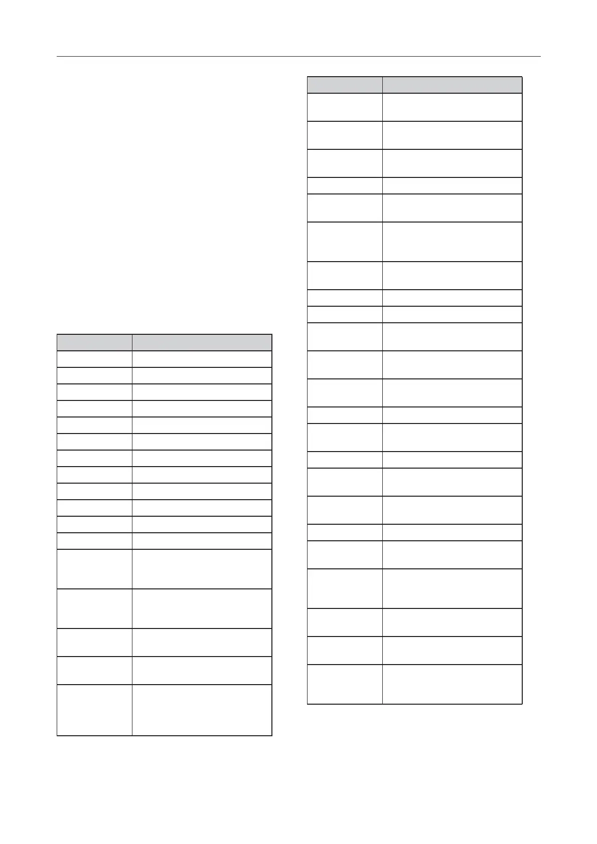
PCB Label Function
SW1 Master RESET button
SW2 MCPU RESET button
SW3 LIOMCU RESET button
SW4 Alarm RESET Button
SW5 Silence Button
SW6 See Table 6, 7 and 8.
SW7 See Table 9, 10, 11 and 12.
J1 See Table 5.
J2 See Table 5.
J3 See Table 5.
J4 See Table 5.
J5 See Table 5.
XT1 Terminals: Alarm Relay 1,
Supervised Inputs 1 and 2, Left
External N-Bus/R-Bus
XT2 Terminals: Fault Relay 2, Iso-
lated Input 1, Isolated Input 2,
Right External N-Bus/ R Bus
XT3 Terminals: Relay 3, Loop A,
Loop B
XT4 Terminals: Relay 4, Loop C,
Loop D
XT5 Terminals: Emergency Alarm
Input, Sounder Output 1,
Sounder Output 2, 24V Power
Outp 1, 24V Power Output 2
Table 3: FC-FI DIP Switches and Connector Functions
XT6 Terminals: 24V and 5V Power
for Third Party Cards
XT7 Terminals: 24V and 5V Power
for Third Party Cards)
XT8 Terminals: 24V Power for
FB800 Fuse Board
XT9 Terminals: PSU connection
XT10 Terminals: Battery and Battery
Thermistor connection
XP1 Connector: Black Box front
panel LEDs: Alarm, Fault, Sys-
tem Fault)
XP2 Connector: I2C interface and
5V Power
XP3 Connector: IO-Bus
XP4 Connector: to the internal GUI
XP6 Connector: External N-Bus for
debugging
XP7 Connector: LIOMCU Debug
port RS232
XP8 Connector: MCPU Debug port
RS232
XP9 Connector: COM1 Printer
XP10 Connector: COM2 FCExpress,
FCChecker
XP11 Connector: COM3 Reserved
XP12 Connector: Auxiliary JTAG for
LIOMCU
XP13 Connector: Auxiliary JTAG for
MCPU
XP14 Connector: USB interface
XP15 Connector: ETHERNET inter-
face
XP16 Connector: Internal N-Bus Ser-
vice Channel signals for debug-
ging
XP17 Connector: Internal N-Bus Loop
Channel signals for debugging
XP18 Connector: Auxiliary JTAG for
CPLD
XP19 Connector: interconnection of
external N-Bus interface with
Redundant MCPU slot card
PCB Label Function
Table 3: FC-FI DIP Switches and Connector Functions