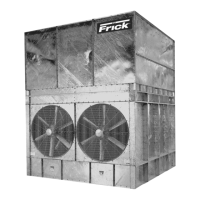
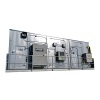
XL EVAPORATIVE COOLING PRODUCTS
INSTALLATION
S140-600 IOM (NOV 07)
Page 4
INSTALLATION TOOLS
To complete the installation of the XL Evaporative Condens-
ers, the following tools are needed:
• Drift pins
• 8-foot straight edge
• Level
• Assorted open-end wrenches
• Socket set
• Belt tension gage
• Tape measure
GENERAL INFORMATION
All XLC and XLP models should be anchored directly to
concrete pads or concrete piers. These units may also be
supported on structural “I” beams as outlined below.
The Centrifugal Fan XLC units are designed to be sup-
ported by two structural “I” beams, one located under each
end of the unit and running the full width of the unit (See
Figure 1a).
The Vane Axial Fan XLP units are designed to be supported
by two structural “I” beams, one located under the front and
one under the rear of the unit, running the full length of the
unit (Figure 1b).
As an alternate, the structural “I” beams may run the full
width of the unit. Please refer to the unit foundation drawings
furnished by Frick for each specifi c sales order for complete
details.
Figure 1b - XLP I-Beam Location On Unit
Figure 1a - XLC I-Beam Location On Unit
adequate/loose fi eld wiring/connections. All personnel must
lock out and tag machinery before working on the condenser.
Proper safety precautions such as the use of insulating
soles/gloves and a trained “lookout buddy” are indispensable.
Ice formation in cold weather can present fall/slip hazards.
Icing safety procedures should be mandatory when the daily
ambient temperature falls below 40°F (4.4°C).
Water Chemistry – All evaporative-cooled condensers op-
erate on principles that encourage biological growth in the
recirculating water unless effective treatment is applied. Re-
circulating water must be periodically analyzed for biological
culture plate counts. XL units should not be operated without
an effective biological treatment program.
NOTE: Emergency “shock” treatment with chemical bio-
cides may upset the unit’s appropriate pH range (creating
an excessively corrosive environment for the materials
of construction) and may expose operators to strong
chemicals that are corrosive or otherwise dangerous
if mishandled (see water treatment comments in the
CHEMICAL TREATMENT section of MAINTENANCE).
Field Piping Considerations for XL Unit Installation – All
IDC units require strongly supported and anchored fi eld pip-
ing. No fi eld piping is to be supported by the XL itself. Wind
loading, temperature variation, etc., must be considered to
allow for movement between the tower, building, optional
vibration isolator/rails, and fi eld piping. A qualifi ed cooling
system design engineer should provide fi nal fi eld-piping
plans and specifi cations.
Before fi nalizing piping installation plans, it is recommended
that related plans for cooling system/plant expansion be
discussed with your fi eld piping/system designer and Imeco
sales representative. Incorporating pipe openings/sizes now
allows for easier installation in the future.
Each beam should be sized in accordance with standard
engineering practices, 55% of the operating weight of the
unit as a uniform load on the beam, allowing for a maximum
defl ection of 1/360 of the length, not to exceed 1/2 inch.

 Loading...


