XL EVAPORATIVE COOLING PRODUCTS
INSTALLATION
S140-600 IOM (NOV 07)
Page 5
All units have 13/16 inch diameter mounting holes for mount-
ing to the beams. The beams should be supported so that the
unit is level. Shims between the beams and the unit should
not be used, as this will not provide adequate support.
If vibration isolation is required, whether furnished by Frick or
by others, the isolators must always be mounted below the
structural “I” beams. Continuous support of unit, as described
above, must be provided.
INSTALLATION
FOUNDATION LAYOUT INFORMATION FOR XLC UNITS
Beams and/or piers should be sized in accordance with
standard engineering practices, 55% of the operating weight
as a uniform load. Beam defl ection should not exceed the
larger of 1/360 of span or 1/2 inch. In Figure 2, “A” repre-
sents the overall length of one cell and “B” represents the
center lines of the mounting holes in the unit. The dashed
lines show the location of the structural beams to which the
unit is mounted.
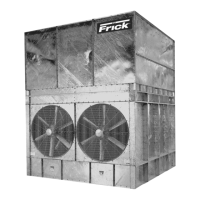
XLC CENTRIFUGAL FAN UNITS
XLC units are shipped in two pieces: the pan/coil section and
the fan section. The fi rst step of the installation is to mount
the pan/coil section on the structural beams and bolt it to the
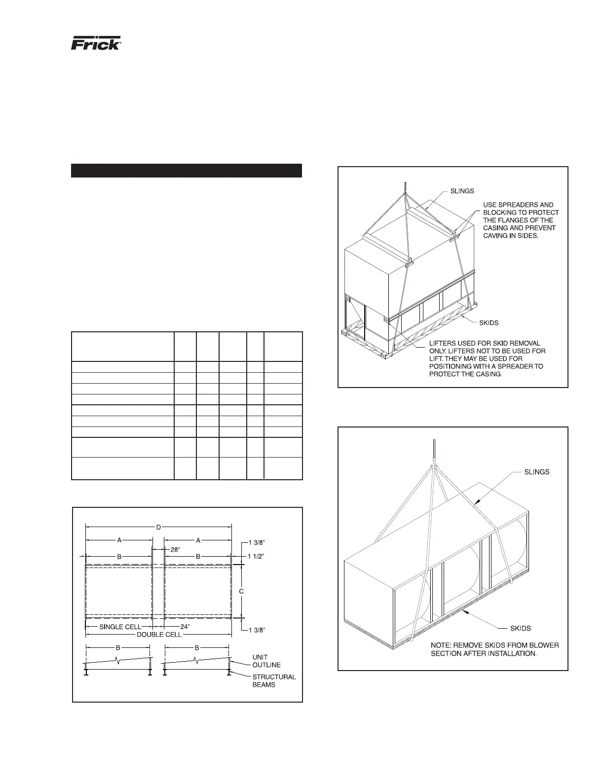
beams. The rigging of the two pieces is shown in Figures 3a
and 3b. For minimum cable length, see Table 1.
Figure 2 - Platform Layout
Table 1
XLC FOUNDATION LAYOUT DIMENSIONS
MIN.
CABLE
MODEL A B C D LENGTH
XLC 25 through XLC 40 57 54 27.25 — 6 ft.
XLC 43 through XLC 55 57 54 38.75 — 6 ft.
XLC 58 through XLC 90 117 114 27.25 — 11 ft.
XLC 95 through XLC 128 117 114 38.75 — 11 ft.
XLC 130 through XLC 185 117 114 57.25 — 11 ft.
XLC 195 through XLC 250 117 114 80.25 — 12 ft.
XLC 285 through XLC 385 177 174 80.25 — 17 ft.
XLC 410-2
through XLC 500-2 117 114 80.25 258 12 ft.
XLC 570-2
through XLC 770-2 177 174 80.25 378 17 ft.
Figure 3a - XLC Pan/Coil Section Rigging
Figure 3b - XLC Fan Section Rigging