XL EVAPORATIVE COOLING PRODUCTS
INSTALLATION
S140-600 IOM (NOV 07)
Page 7
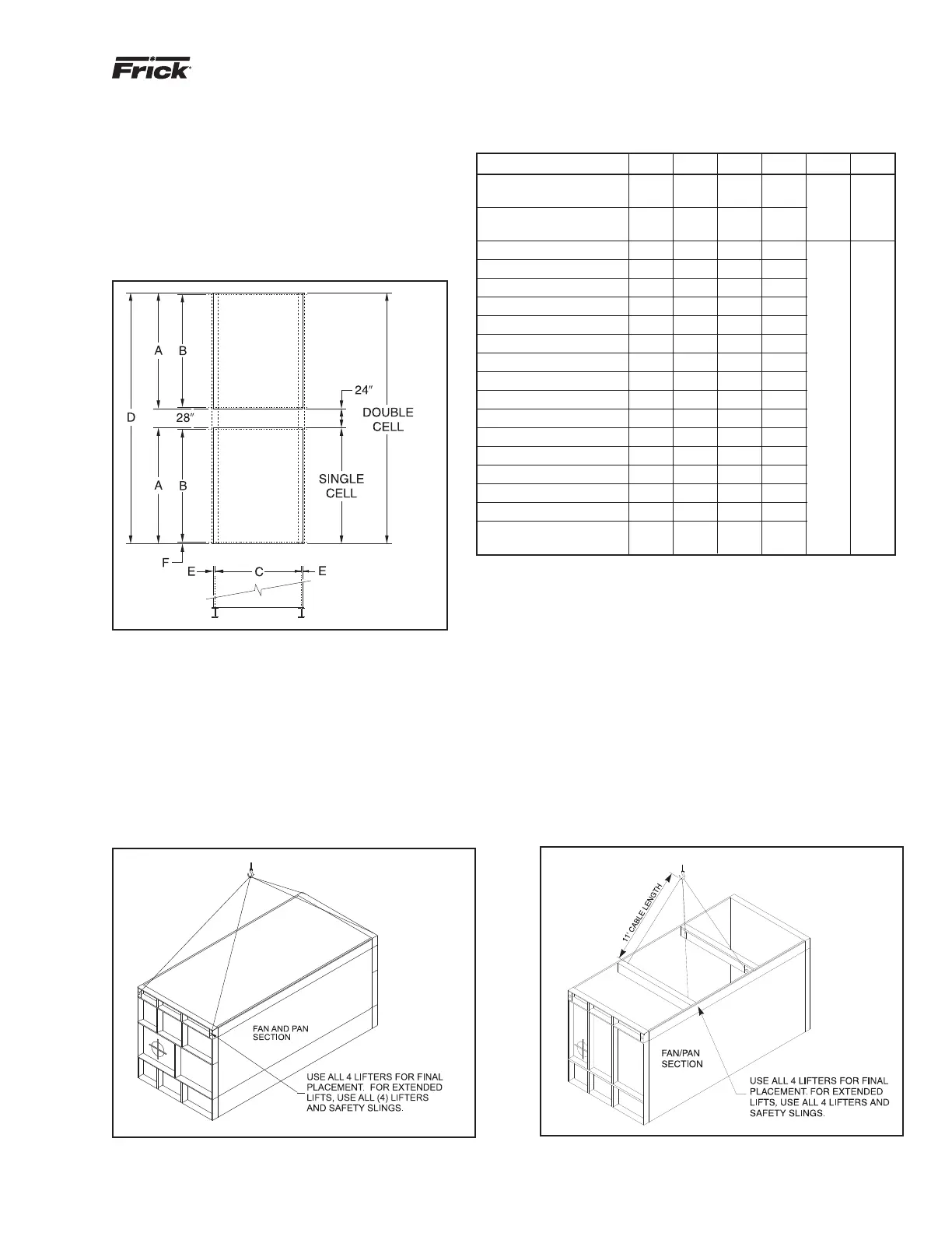
FOUNDATION LAYOUT INFORMATION
FOR XLP UNITS
Beams and/or piers should be sized in accordance with
standard engineering practices, 55% of the operating
weight as a uniform load. Beam defl ection should not
exceed 1/360 of span, or maximum of 1/2 inch. In Figure
6, “A” represents the overall length of one cell and “B”
represents the center lines of the mounting holes in the
unit. The dashed lines show the location of the structural
beams to which the unit is mounted.
Figure 6 - Platform Layout
INSTALLING XLP SINGLE LENGTH UNIT
XLP units are shipped in two pieces, the pan/fan section and
the coil section. The fi rst step of the installation is to mount
the fan/pan section on the structural beams with bolts. The
rigging of the two pieces is shown in Figures 7a through 7c.
For cable lengths, see Table 3.
Figure 7a - XLP Fan Section Rigging (All models
except 1570-2 and 1660-2 through 1880-2)
Figure 7b - XLP Fan Section Rigging (Models 1570-2
and 1660-2 through 1880-2)
MODEL A B C D E F
S90 thru S175
S185,S190,S200,S205
145 141 57.5 —
1.625 0.75
S180, S195
S210 thru S270
145 141 68.5 —
M155 thru M280 121.87 117.87 92 —
M285 thru M430 177 173 92 —
M810-2 thru M960-2 177 173 92 378
ML235 thru ML345 145 141 92 —
L350 thru ML520 211 207 92 —
ML820-2 thru ML1040-2 211 207 92 446
L290 thru L415 145 141 112 —
L435 thru L700 211 207 112 —
L810-2 thru L830-2 145 141 112 314 2.125 2
L870-2 thru L1400-2 211 207 112 446
XL355 thru XL530 145 141 137 —
XL535 thru XL805 211 207 137 —
XL785, 830 – 940 245 241 137 —
XL830-2 thru XL1060-2 145 141 137 314
XL1070-2 thru XL1650-2 211 207 137 446
XL1570-2 and
245 241 137 514
XL1660-2 thru XL1880-2
TABLE 2
XLP FOUNDATION LAYOUT DIMENSIONS