130 4280 010 E
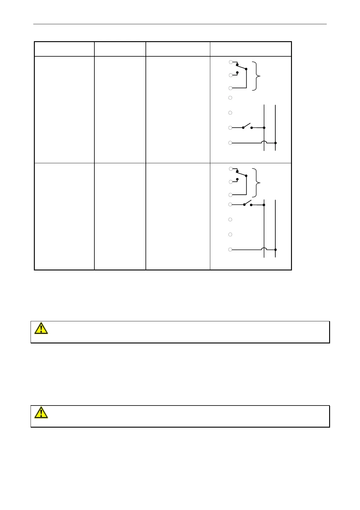
Actuator
Configuration
Terminal
Markings
Terminal
Connections
Wiring Diagram
On-Off + CPI
7
8
9
6
3
4
N
Opening Contact
Closing Contact
Common
None
None
On-Off
System Neutral
6
on
L
N
M
(1)
(5)
3
4
N
7
8
9
CPI
On-Off + CPI + MR
7
8
9
6
3
4
N
Opening Contact
Closing Contact
Common
On-Off
None
None
System Neutral
6
on
L
N
M
(1)
(5)
3
4
N
7
8
9
CPI
Table 1: Electrical connections
With the gas line closed, apply power to the actuator and move the valve at least three times through the complete
stroke range to ensure faultless operation.
Checkout Procedure
WARNING: Fire or explosion hazard. Avoid personal injury or property damage by ensuring that the valve
functions properly and there are no gas leaks. Follow this checkout procedure before leaving the installation.
• Close the upstream shutoff cock and connect air tubing with a maximum of 1 psi (70 mbar) pressure to the
inlet pressure connection.
• Paint the pipe connections of the valve with a rich soap and water solution (or use acceptable gas leak
detection equipment) to check for leakage. Open the upstream shutoff cock. If bubbles occur, this is an
indication of a gas leak. To stop a leak, tighten joints and pipe connections. Replace the part if the leak cannot
be stopped.
• Refer to the Adjustments section to make any necessary valve setting adjustments.
WARNING: Fire or explosion hazard. Valve settings must be in accordance with the manufacturer’s
specifications.
• Before leaving the installation, observe at least three complete operating cycles to ensure that all components
are functioning correctly.
Johnson Controls SA/NV - Leuvensesteenweg 248D - B-1800 Vilvoorde - +32(2) 709 40 00 - www.johnsoncontrols.be