Johnson Controls
5586996-JSG-A-0120 | Start-Up & Operation Guide
Phase Monitor Adjustment
To adjust the phase monitor trip points, review the in-
structions in Phase Monitor Checks and Adjustments
in the Maintenance section of the Johnson Controls
Premier 25–50 Ton Rooftop Units Installation and
Maintenance Manual (Form 5586959-JIM).
20
7. Adjust the low re manifold pressure:
a. Place the heat section into low fire operation.
b. Compare low fire manifold pressure to Table
9.
c. Remove the cap from the low fire pressure
regulator.
d. Use a 3/32 inch Allen wrench to make the
manifold pressure adjustment. Increase
manifold pressure by turning the screw clock-
wise; decrease manifold pressure by turning
the screw counterclockwise.
e. Place a finger over the adjustment opening
while verifying the manifold pressure.
8. Turn OFF the heat.
9. Turn OFF the gas.
10. Remove the brass tubing adapter and replace
the plug in the outlet pressure tap.
Commissioning Mode
Commissioning mode is a function used for manually
operating the unit during a service call or commission-
ing demonstration. It allows for the unit components
to be operated individually. The unit must not be op-
erated in this mode for an extended period, therefore
commissioning mode terminates automatically after 60
minutes unless extended at the local unit display for
another 60 minutes.
Cooling and heating is disabled unless supply fan sta-
tus is proven. Unit protection and safeties remain ac-
tive and logged during commissioning mode.
When a compressor is manually turned on, a condens-
er fan in the associated refrigeration circuit is automati-
cally turned on. This is to protect the compressor from
a high-pressure condition.
See Commission > Commissioning Mode > Air Handler,
Cooling, and Heating menus in Table 28 on page 71.
Air Balancing Wizard
The air balancing wizard is a grouping of configuration
screens used for testing and calibrating airflow measur-
ing stations (AMS), overriding damper positions, over-
riding fan speeds, and other functions to assist service
technicians and air balancers. See Table 11.
When the air balancer mode is set to enable, all heating
and cooling stages are disabled via the state table.
When the air balancer mode is set to disable, either from
the user or from a fixed 60 minute time-out value, all
overrides are set back to none.
See Commission > Air Balance > Supply, Return, and
Exhaust menus in Table 28 on page 68.
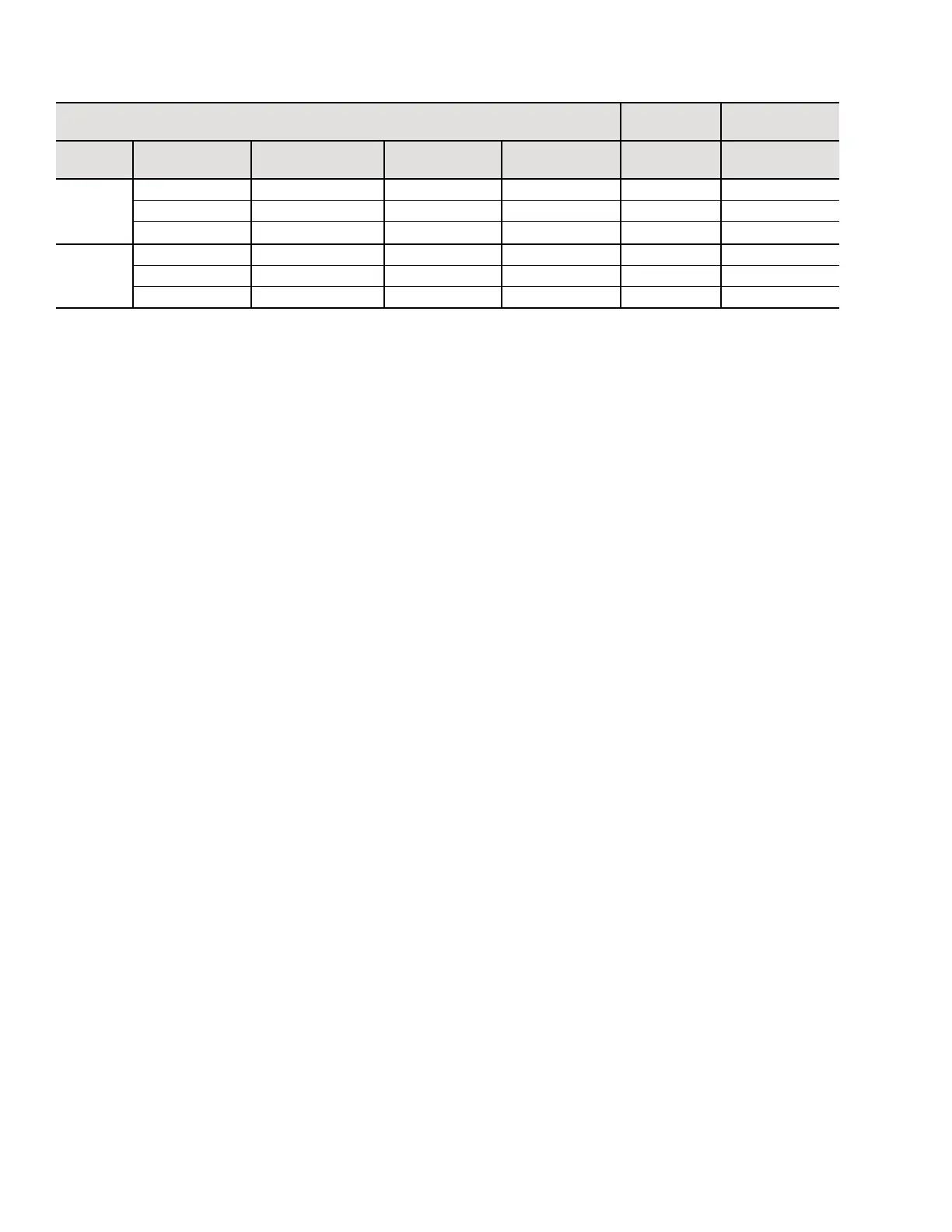
Table 10: Staged and Modulating Gas Heat
Staged and Modulating Gas Heat
Staged Gas
Heat
Modulating Gas
Heat
Model
Gas Input
Capacity (MBH)
Maximum Output
Capacity (MBH)
Minimum
Airow (CFM)
Gas Connection
Size (inches)
Steps Turndown
25–30
250 202.5 5,000 1.00 2 10:1
500 405 5,000 1.00 2 20:1
750 607.5 5,000 1.00 4 30:1
40–50
500 405 8,000 1.25 2 20:1
750 607.5 8,000 1.25 4 30:1
1250 1012.5 8,000 1.25 6 50:1
NOTES:
For proper operation, the building supplied natural gas pressure should be 7–14 iwg (liquid propane pressure should be 12–14 iwg).
Temperature rise can be calculated where temperature rise = (gas input capacity (Btu) x 0.81) / (CFM x 1.085).
Maximum leaving air temperature cannot exceed 120.0°F
 Loading...