Liquid-line filter drier
This unit requires a bi-flow liquid line filter drier installed
external to the unit. This is included in the wiring
accessory kit HMH7AK001 required for installation.
R-410A filter-drier
Source 1 Part Number
Apply with models
S1-404101 All
NOTICE
Using a larger than specified line size could result
in oil return problems. Using too small a line results
in loss of capacity and other problems caused by
insufficient refrigerant flow. For the heat pump,
maintain level horizontal refrigerant lines between the
indoor unit and the outdoor unit to facilitate sufficient
oil return.
Add-on replacement/retrofit
When using this unit as a replacement for an existing
R-410A unit, these are matched systems. Replace
the indoor coil and the outdoor unit. Perform the
following steps to ensure correct system operation and
performance.
1. Change out the indoor coil to an approved R-410A
coil/air handling unit combination with the
appropriate metering device.
2. Change out the lineset when replacing an R-22 unit
with an R410A unit to reduce cross-contamination of
oils and refrigerants. If change-out of the lineset is
not practical, take the following precautions:
a. Inspect the lineset for kinks, sharp bends, or
other restrictions, and for corrosion.
b. Determine if there are any low spots that
might be serving as oil traps.
c. Flush the lineset with a commercially available
flush kit to remove as much of the existing oil
and contaminants as possible.
3. If replacing the outdoor unit because of a
compressor burnout, replace the refrigeration lines
or, at a minimum, thoroughly flush the lines with a
commercially available flush kit.
WARNING
Never install a suction-line filter drier in the liquid line
of an R-410A system. Failure to follow this warning
can cause a fire, injury, or death.
Precautions for line installation
Adhere to the following during line installation:
• Connect the outdoor unit to the indoor coil using
field supplied refrigerant grade (ACR) copper tubing
that is internally clean and dry. Units must only be
installed with the tubing sizes for approved system
combinations as specified in the Tabular Data Sheet.
The charge given is applicable for total tubing
lengths up to 15 ft (4.6 m).
• Install the refrigerant lines with as few bends as
possible. Ensure not to damage the couplings or
kink the tubing. Use clean hard drawn copper tubing
where no appreciable amount of bending around
obstruction is necessary. If soft copper must be
used, ensure to avoid sharp bends that may cause a
restriction.
• Install the lines so that they do not obstruct service
access to the coil, indoor section, or filter.
• Isolate the refrigerant lines to minimize noise
transmission from the equipment to the structure.
• Insulate the vapor line with a minimum of 1/2-in.
foam rubber insulation (Armaflex or equivalent).
Insulate liquid lines that may be exposed to direct
sunlight, high temperatures, or excessive humidity.
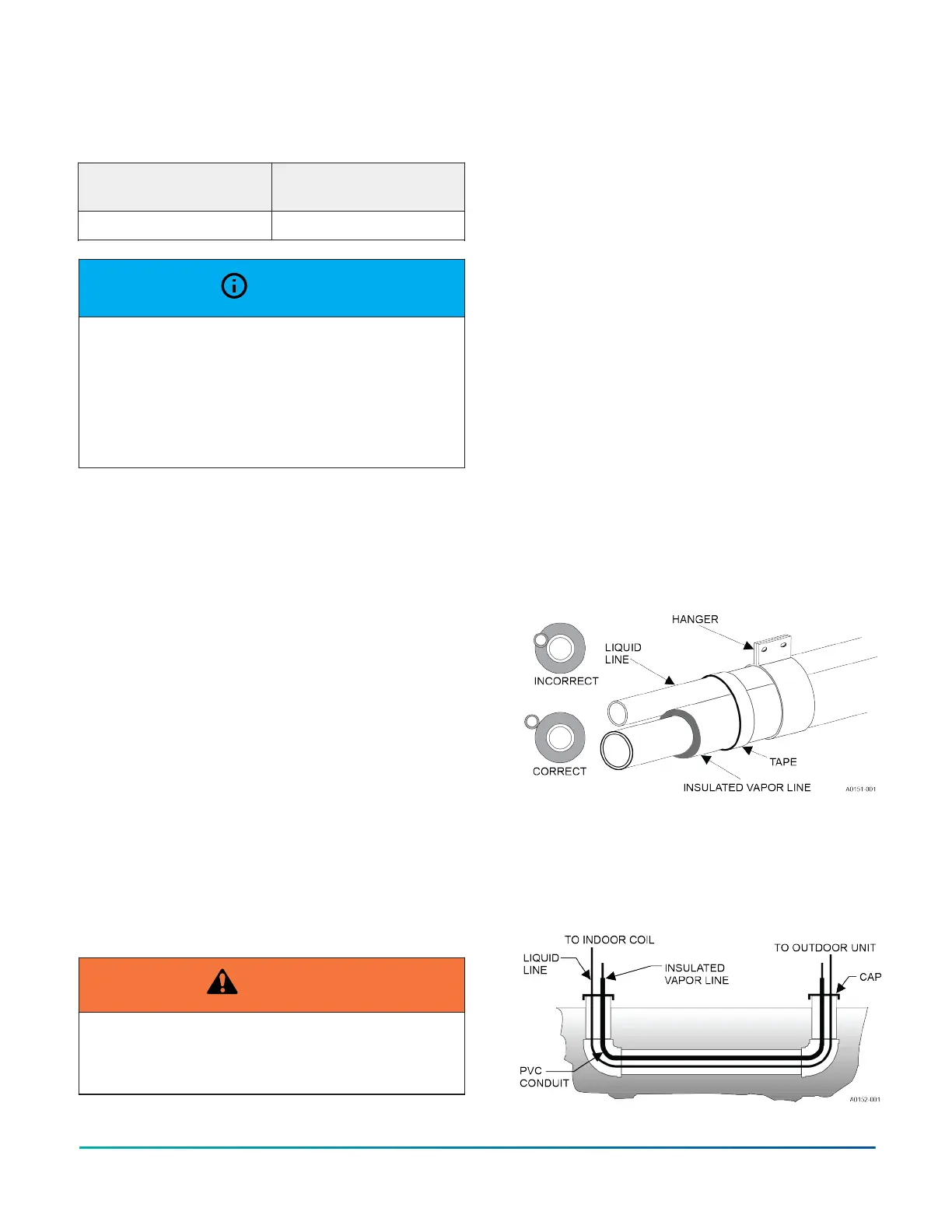
• Tape and suspend the refrigerant lines correctly. Do
not allow tube metal-to-metal contact. See Figure 2.
Figure 2: Installation of vapor line
• Use PVC piping as a conduit for all underground
installations as shown in Figure 3. Keep buried lines
as short as possible to minimize the build up of liquid
refrigerant in the vapor line during long periods of
shutdown.
Figure 3: Underground installation
Installation Manual: HMH7 Series - 17 SEER Horizontal Discharge Modulating Heat Pump 7
Johnson Controls Ducted Systems

 Loading...


