6112628-UIM-B-0622
Johnson Controls Ducted Systems 9
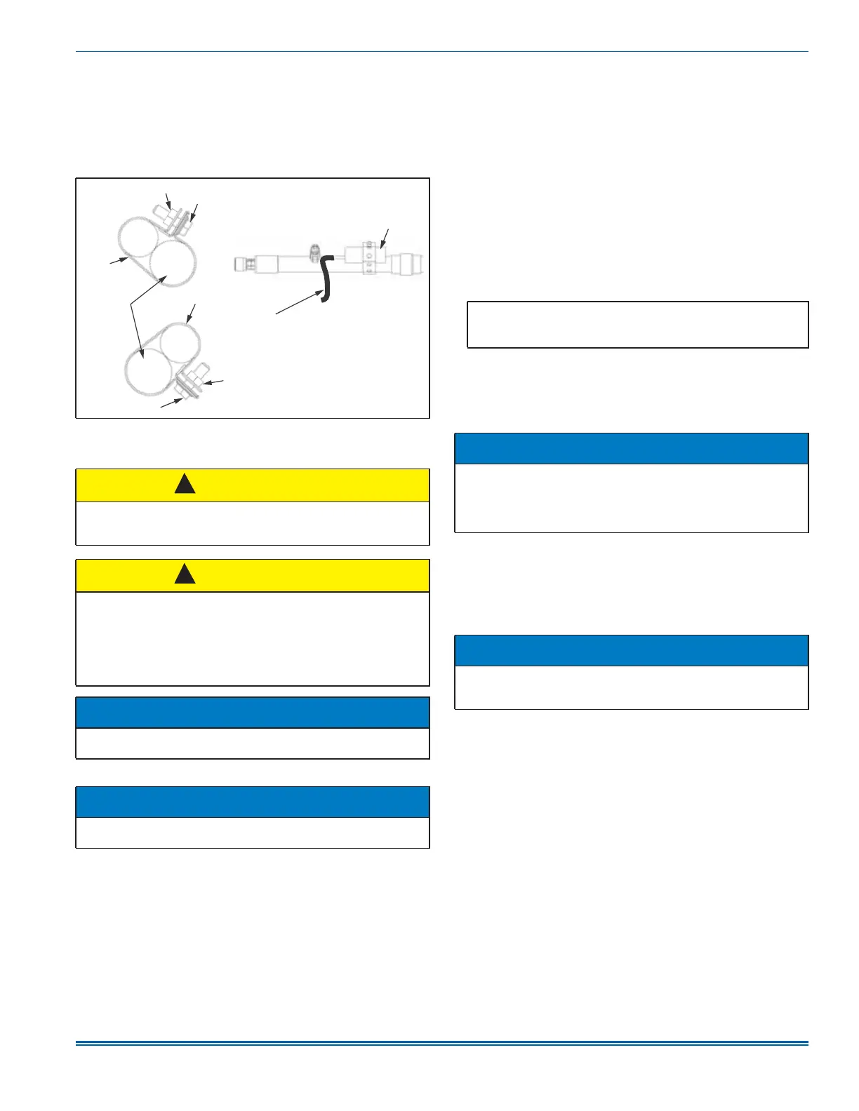
a. Install the TXV bulb on the vapor line suction header near the
TXV equalizer tube connection port. Ensure to install the bulb at
a 10 o’clock or 2 o’clock position.
b. Insulate the TXV bulb using the thermal insulation provided to
protect it from the effect of the surrounding ambient temperature.
Cover the bulb completely to insulate.
9. After installing the refrigeration piping, leak test the system.
Section VI: Refrigerant line connection
Connect lines as follows:
1. Make suction and liquid line connections outside of the cabinet.
Leave the tubing connection panel attached to the cabinet. Remove
the coil access panel for brazing. The lines are expanded to receive
the field refrigeration piping tubes for most outdoor unit matches.
2. Remove the grommets where the tubes exit the cabinet to prevent
burning them during brazing. In some units, the grommets may be
shipped as loose parts with the unit. See Figure 14.
3. Cut the end of the suction tube using a tube cutter. Place the tube
cutter as close as possible to the end of the tube to allow as much
depth as possible for the connection and brazing of the suction line.
To ensure the suction line fits into the connection, deburr the stub
out (including inner pressure protrusion from cutting).
4. If the coil does have a factory installed TXV or EEV, go to Step 5. If
the coil does not have a factory installed TXV or EEV, install the
required size piston or TXV kit. See Coil metering devices and Pis-
ton installation or Thermal expansion valve (TXV) installation for
detailed instructions.
5. If the coil does have a factory installed TXV or EEV, remove the liq-
uid line copper cap that is soft soldered onto the outside of the 3/8
in. stub protruding from the front of the coil cabinet tubing panel:
a. Screw a sheet metal screw into the center of the cap.
b. Apply a small amount of heat to the cap while pulling on the
screw using slip joint pliers.
Before brazing, connect and apply line power to the field wiring
terminals of the air handling unit and ensure the board is pow-
ered for 60 s. This ensures the EEV control board cycles the
valve to an open position. This allows nitrogen to flow through
the system during brazing.
6. Insert the liquid and suction lines into the coil connections at the coil
cabinet tubing panel.
7. Wrap a water-soaked rag around the coil connection tubes inside
the cabinet to avoid transferring excess heat to the coil, TXV, EEV,
and temperature sensor if the coil is equipped with an EEV.
8. Purge the refrigerant lines with dry nitrogen during brazing.
9. Braze the suction and liquid lines, and allow the joints to cool.
10. Secure the sensing bulb and equalizer line capillary tubes with
nylon cable ties to prevent leaks from tubes rubbing.
11. If using a piston, install a Schrader valve core into the suction
header and reinstall the cap.
12. Re-attach the grommets to the lines carefully to prevent air leakage.
In some units, the grommets may be shipped as loose parts with
the unit. See Figure 14.
13. Refer to the outdoor unit Installation Manual and complete evacua-
tion, a leak check, and charging instructions. Check all field brazed
joints and metering device connections.
14. Attach the coil access panel to the cabinet.
15. Ensure the lines are sound isolated by using appropriate hangers
or strapping.
Figure 13: Correct bulb location
CAUTION
The coil is under inert gas pressure. Relieve pressure from the coil by
depressing the Schrader valve core at the end of the suction manifold
stub out.
CAUTION
Dry nitrogen must always be supplied through the tubing while it is
being brazed, because the temperature required is high enough to
cause oxidation of the copper unless an inert atmosphere is provided.
The flow of dry nitrogen must continue until the joint has cooled.
Always use a pressure regulator and safety valve to insure that only
low pressure dry nitrogen is introduced into the tubing. Only a small
flow is necessary to displace air and prevent oxidation.
NOTICE
Avoid handling aluminum coil components after handling the copper
refrigeration piping or other tubing without first cleaning hands.
NOTICE
Route the refrigerant lines to the coil in a manner that will not obstruct
service access to the coil, air handling system, furnace flue, or filter.
A1672-001
Nut
Screw
Bulb at
10 o’clock
position
Clamp
Vapor line
Bulb at
2 o’clock
position
Screw
Nut
Clamp
TXV bulb
TXV sensing bulb
Indoor coil header assembly
(connecting bulb with evaporator TXV)
(header body)
!
!
Important: For EEV-equipped coils only
The EEV in this unit is shipped in the closed position to protect the
valve during transportation.
NOTICE
If power cannot be applied to the EEV control board prior to brazing
refrigeration piping, a tool is available to manually operate the EEV.
An EEV manual operating tool can be purchased from Source 1 as
part number S1-02649686000. Six revolutions of the tool opens the
valve fully.
NOTICE
All indoor coil connections are copper-to-copper and must be brazed
with a phosphorous-copper alloy material such as Silfos-5 or equiva-
lent. Do not use soft solder.