6139716-UIM-A-0422
Johnson Controls Ducted Systems 11
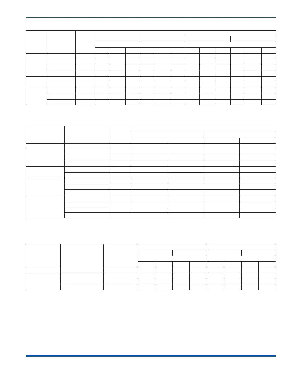
Table 11: Electrical data for multi-source power supply: 208/230-1-60
Air
handlers
models
Heater
models
1
Heater
amps (A)
at 240 V
Minimum circuit ampacity (A)
MOP
2
(A)
208 V 230 V 208 V 230 V
Circuit Circuit
First
2
Second Third
First
2
Second Third
First
2
Second Third
First
2
Second Third
JMET12B
8HK16501506 60 26.2 43.5 — 28.4 48.1 — 30 45 — 30 50 —
8HK16502006 80 48 43.3 — 52.6 47.8 — 50 45 — 60 50 —
JMET12C
8HK16501506 60 26.2 43.5 — 28.4 48.1 — 30 45 — 30 50 —
8HK16502006 80 48 43.3 — 52.6 47.8 — 50 45 — 60 50 —
JMET16C
8HK16501506 60 28.2 43.5 — 30.4 48.1 — 30 45 — 35 50 —
8HK16502006 80 50 43.3 — 54.6 47.8 — 50 45 — 60 50 —
JMET18D
8HK16501506 60 28.2 43.5 — 30.4 48.1 — 30 45 — 35 50 —
8HK16502006 80 50 43.3 — 54.6 47.8 — 50 45 — 60 50 —
8HK16502506 100 50 43.3 21.6 54.6 47.8 23.9 50 45 25 60 50 25
1. 8HK1 = with service disconnect, no breaker jumper bar
2. MOP = Maximum Overcurrent Protection device; must be HACR type circuit breaker or time delay fuse. The first circuit includes blower motor amps. Refer to the lat-
est edition of the National Electric Code or in Canada the Canadian electrical Code and local codes to determine correct wire sizing.
Table 12: Electrical data for single source power supply: 208/230-3-60
Air handler models
Heater models
1
Heater
amps (A)
at 240 V
Field wiring
Minimum circuit ampacity (A)
MOP
2
(A)
208 V 230 V 208 V 230 V
JMET08B 8HK06501025 23.1 28.2 30.9 30 35
JMET12B
8HK06501025 23.1 29.7 32.4 30 35
8HK06501525 34.6 42.2 46.2 45 50
8HK16502025
1
46.2 54.7 60 60 60
JMET12C
8HK06501025 23.1 29.7 32.4 30 35
8HK06501525 34.6 42.2 46.2 45 50
JMET16C
8HK06501025 23.1 31.7 34.4 35 35
8HK06501525 34.6 44.2 48.2 45 50
8HK16502025
1
46.2 56.7 62 60 70
JMET18D
8HK06501025 23.1 31.7 34.4 35 35
8HK06501525 34.6 44.2 48.2 45 50
8HK16502025
1
46.2 56.7 62 60 70
8HK16502525
1
57.7 69.2 75.8 70 80
1. 0 = no service disconnect or 1 = with service disconnect. The 20 kW and 25 kW heater models (8HK16502025 and 8HK16502525) come with service disconnects
standard. Single source power MCA and MOP requirements are given here only for reference if used with field installed single point power modification.
2. MOP = Maximum overcurrent protection device; must be HACR type circuit breaker or time delay fuse. The first circuit includes blower motor amps. Refer to the lat-
est edition of the National Electric Code or in Canada the Canadian electrical Code and local codes to determine correct wire sizing.
Table 13: Electrical data for multi-source power supply: 208/230-3-60
Air handlers
models
Heater
models
1
Heater amps (A)
at 240 V
Minimum circuit ampacity (A)
MOP
2
(A)
208 V 230 V 208 V 230 V
Circuit Circuit
First
2
Second
First
2
Second
First
2
Second
First
2
Second
JMET12B 8HK16502025 46.2 29.7 25 32.4 27.6 30 25 35 30
JMET16C 8HK16502025 46.2 31.7 25 34.4 27.6 35 25 35 30
JMET18D
8HK16502025 46.2 31.7 25 34.4 27.6 35 25 35 30
8HK16502525 57.7 38 31.2 41.3 34.5 40 35 45 35
1. The 20 kW and 25 kW heater models (8HK16502025 and 8HK16502525) come with circuit breakers standard.
2. MOP = Maximum overcurrent protection device; must be HACR type circuit breaker or time delay fuse. The first circuit includes blower motor amps. Refer to the lat-
est edition of the National Electric Code or in Canada the Canadian electrical Code and local codes to determine correct wire sizing.
 Loading...