6139716-UIM-A-0422
2 Johnson Controls Ducted Systems
Safety requirements
• Failure to carefully read and follow all instructions in this manual
can result in air handler malfunction, death, personal injury, or
property damage.
• Always install this air handler in accordance with all national and
local building and safety codes and requirements, local plumbing
or wastewater codes, and other applicable codes.
• Only install this air handler in a location and position specified in
the Unit installation.
• Do not use the air handler for temporary heating of buildings or
structures under construction.
• Always install the air handler to operate within the air handler’s
intended maximum outlet air temperature.
• Clearance from combustible material is provided under Clear-
ances in Unit installation.
• The unit rating plate displays the air handler model number. The
unit dimensions for the supply air plenum are provided in Figure
2 and Table 1. Always install the plenum according to the instruc-
tions.
• It is necessary to maintain clearances for servicing and allow
access to the electric heaters and blower.
• It is necessary to verify the unit rating plate and power supply to
ensure that the electrical characteristics match.
• When attaching ductwork with screws, carefully fasten the screws
and keep them within 5/8 in. of the sides and back of the air han-
dler.
• Installing and servicing heating and cooling equipment can be
hazardous due to the electrical components. Only trained and
licensed personnel must install, repair, or service heating and
cooling equipment. Unlicensed service personnel can perform
basic maintenance functions such as cleaning and replacing the
air filters. When working on heating and cooling equipment, the
precautions in the manuals and on the labels attached to the unit
and other safety precautions must be observed as applicable.
• Install the air handler so the electrical components are protected
from water.
• These instructions cover minimum requirements and conform to
existing national standards and safety codes. In some instances,
these instructions exceed certain local codes and ordinances,
especially those who have not kept up with changing residential
and non-HUD modular home construction practices. These
instructions are required as a minimum for a safe installation.
• These models are not CSA listed or approved for installation into
a HUD-approved modular home or a manufactured (mobile)
home.
WARNING
This appliance is not intended for use by persons (including children)
with reduced physical, sensory or mental capabilities, or lack of expe-
rience and knowledge, unless they have been given supervision or
instruction concerning use of the appliance by a person responsible
for their safety.
Children should be supervised to ensure that they do not play with the
appliance.
WARNING
Improper installation, adjustment, alteration, or maintenance may cre-
ate a condition where the operation of the product could cause per-
sonal injury or property damage. Refer to this manual for assistance,
or for additional information, consult a qualified contractor, installer, or
service agency.
CAUTION
This product must be installed in strict compliance with the installation
instructions and any applicable local, state, and national codes
including, but not limited to building, electrical, and mechanical codes.
NOTICE
To ensure a correct match for this indoor product, refer to the current
Tabular Data Sheet for the outdoor equipment selected for the system
application. If the indoor product model is not listed in the Tabular
Data Sheet included with the outdoor unit, to access the current ver-
sion of the Tabular Data Sheet, go to the Residential Equipment and
Supplies section of the Offering Catalog at
www.simplygettingthejobdone.com or scan the QR code provided on
the outdoor unit rating plate.
!
!
!
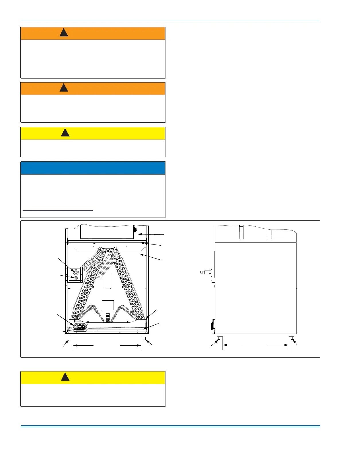
Figure 1: Return air duct attachment and component location
A1756-001
Screw
Ductwork
Front view
Blower compartment
Cabinet brace
Coil compartment
(access panel removed)
Primary drain pan
Cabinet brace
Screw
Side view
Ductwork
Screw
Screw
Secondary drain
upflow 3/4-in. NPT
Vapor refrigerant
line connection
Liquid refrigerant
line connection
Primary drain
3/4 in. NPT
CAUTION
These air handlers must be transported and handled in an upright,
upflow position. Failure to do so may result in unit damage and per-
sonal injury. Configuration conversions must be done at the site of
installation.
!