6139716-UIM-A-0422
Johnson Controls Ducted Systems 5
Section IV: Ductwork and connections
Air supply and return may be handled in one of several ways best
suited to the installation. Upflow, horizontal or downflow applications
may be used.
The vast majority of problems encountered with heating and cooling
systems can be linked to incorrectly designed or installed duct systems.
It is therefore highly important to the success of an installation that the
duct system be correctly designed and installed.
When installing a central air return grille in or near the living space,
design the ductwork so that the grille is not in direct line with the open-
ing in the unit. One or two elbows and acoustical duct liner assure a qui-
eter system. For operation where the return air duct is short or where
sound may be a problem, use acoustical duct liner inside the duct. Use
flexible duct connectors to minimize the transmission of vibration and
noise into the conditioned space.
Insulation of ductwork is imperative where it runs through an unheated
space during the heating season or through an uncooled space during
the cooling season.
Use a vapor barrier to prevent absorption of moisture from the sur-
rounding air into the insulation.
Use a transition to match unit opening to correctly size the supply air
duct. Suspend all ducts using flexible hangers and never fasten directly
to the structure.
Ductwork must be fabricated and installed in accordance with local and/
or national codes. This includes the standards of the National Fire Pro-
tection Association for Installation of Air-Conditioning and Ventilating
Systems, NFPA No. 90B. If using electric heat, non-flammable material
must be used. Duct systems must be designed in accordance with
ACCA Manual D.
Horizontal suspension
It is possible to suspend these air handlers in horizontal applications.
Use angle steel support brackets with minimum 3/8 in. threaded rods,
supporting the unit from the bottom. Attach the threaded rods at the
locations shown in Figure 7 or Figure 8, leaving enough clearance
between the door and the rod so that doors can be easily removed for
service.
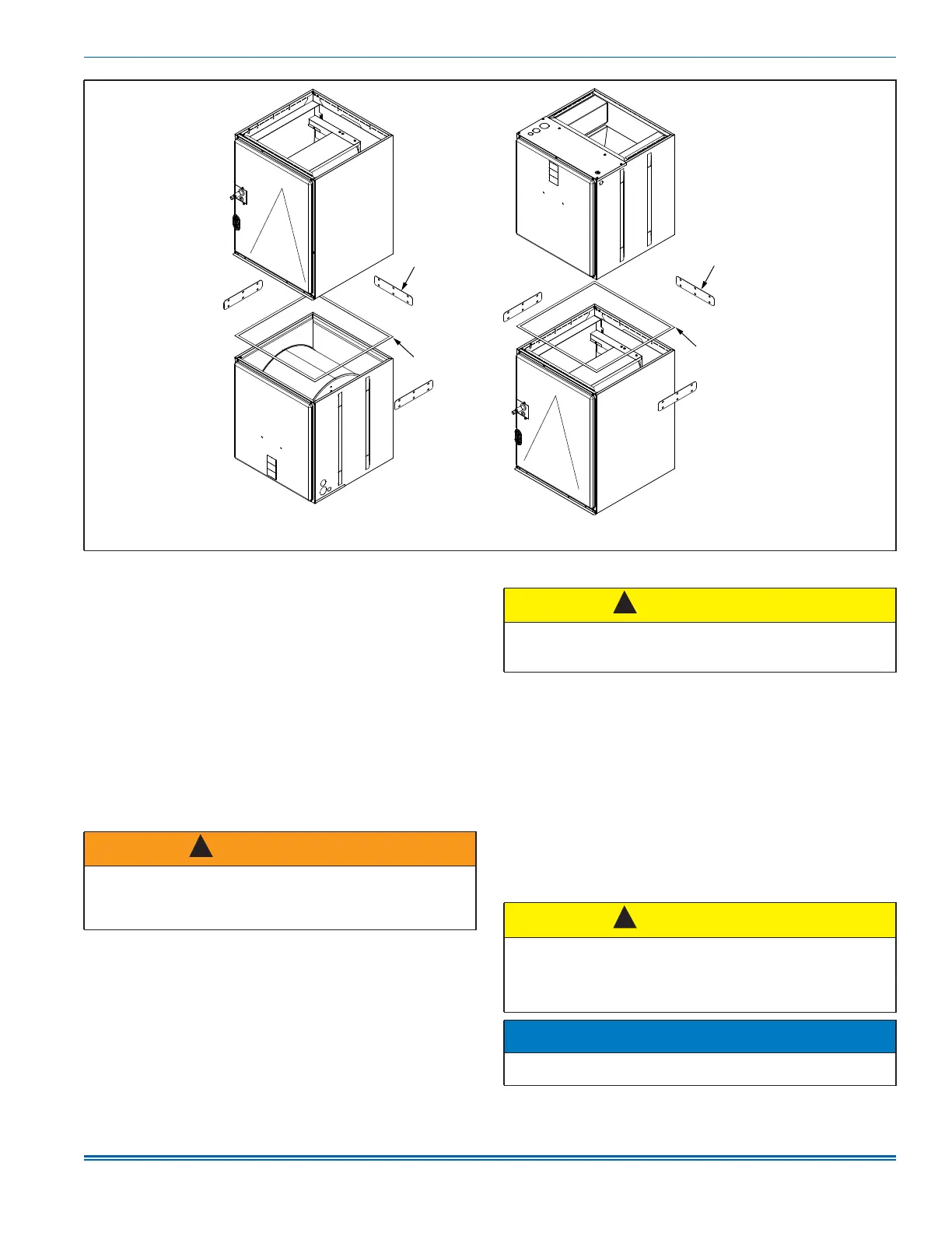
Figure 6: Gasket location
Tie plate
Tie plate
Gasket
Gasket
Downflow
Upflow
A1758-001
WARNING
Do not bring in return air from a location which could introduce haz-
ardous substances into the airflow.
Use 1/2 in. screws to connect ductwork to the cabinet. If pilot holes
are drilled, drill only through the field duct and the unit flange.
!
CAUTION
This unit is not designed for non-ducted (freeblow) applications. Do
not operate without ductwork attached to the unit.
Never operate the equipment without filters.
CAUTION
Do not lift the air handler by the cabinet brace. The cabinet brace is
held in place by the coil channel. The cabinet brace could become
disengaged from the cabinet causing the air handler to fall, potentially
causing injury or damaging property. See Figure 1 for the location of
the cabinet braces.
NOTICE
When assembling the support structure, size to provide clearance for
access door removal.
!
!