LN Series Free Programmable LN-PRGxxx-12 Controllers Installation Instructions 7
Input Wiring
The controllers have physical connections for inputs,
which are software configurable from within the
device’s Graphical Programming Interface (GPI) LN
plug-in, the LN plug-in when using LN Builder, or the
LN wizard when using the BSC Workbench. Each input
can be configured for digital, resistive, current, or
voltage signals. You must configure the input types
properly in the software plug-in or wizard to ensure
proper input readings.
Note: For wire length less than 75 feet (23 m), use
either a shielded or unshielded 18 AWG wire.
Note: For a wire up to 200 feet (61 m) long, a shielded
18 AWG wire is recommended.
Note: The wire should be shielded on the controller
side and the shield length should be kept as short as
possible.
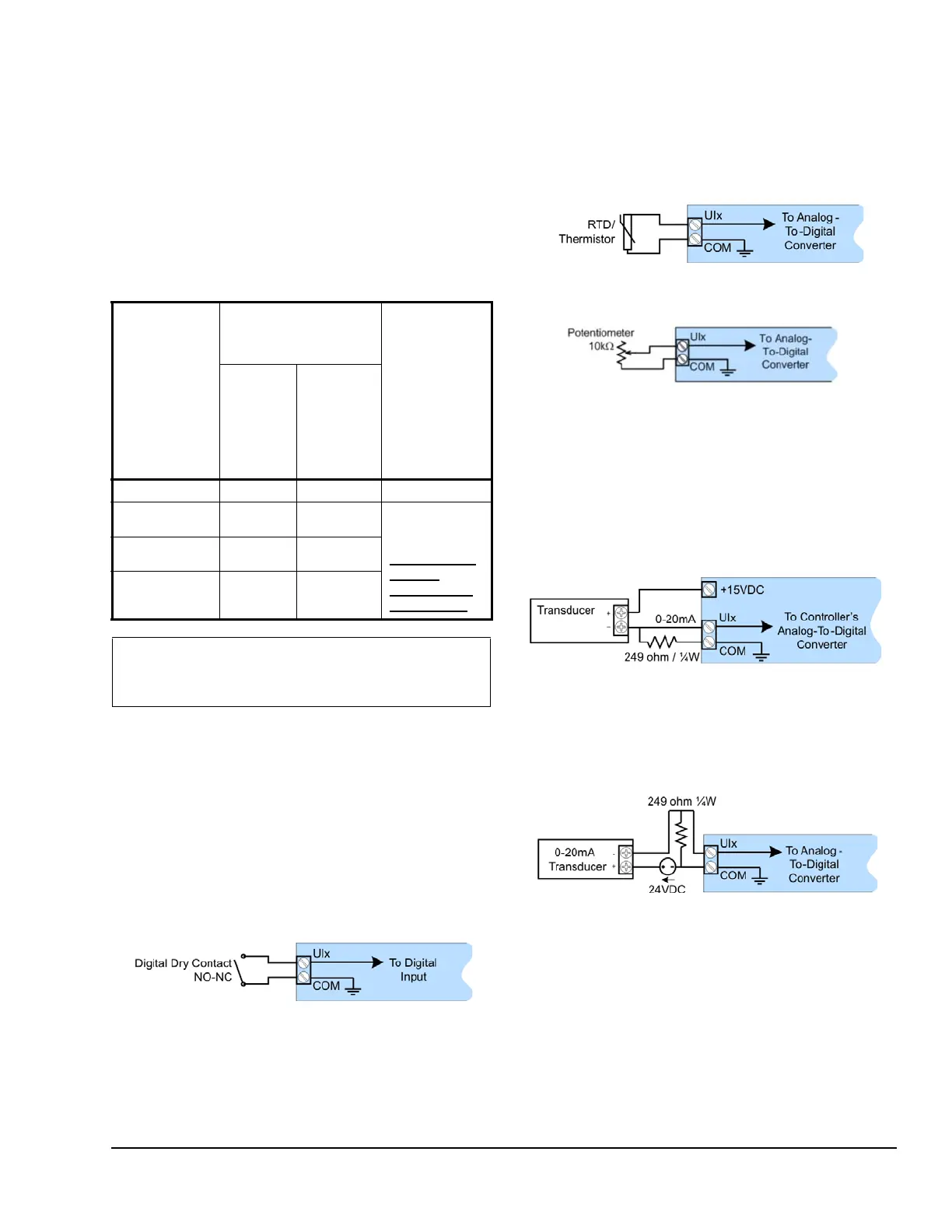
Wiring Digital Inputs
Use this input configuration to monitor digital dry
contacts, as well as pulsed contacts.
Wiring Resistive Inputs
Use this input configuration to monitor Resistance
Temperature Detectors (RTD); thermistors, such as
1,000 ohm RTDs to 10k ohm Type II and Type III
thermistors; and potentiometers, such as 10k ohm and
100k ohm.
Wiring Current Inputs
Current inputs have a range of 0 to 20 mA. Depending
on the transducer power requirements, you may use
any of the following input configurations. Use Figure 12
for the 2-wire, 0 to 20 mA transducer powered by the
controller’s internal 15 VDC power supply.
Use the Figure 13 configuration for a 2-wire, 0 to 20
mA transducer powered by an external 24 AC/DC
power supply.
Table 1: Controller Input Support
Controller Fast and Slow
Pulse Inputs
support
Current
Input
Jumper
support: 0 to
10 VDC/0 to
20 mA
50 Hz: 10
ms
minimum
ON/OFF
(Fast
Pulse)
1 Hz: 500
ms
minimum
ON/OFF
(Slow
Pulse)
LN-PRG203-12
none Ul1 to Ul6 none
LN-PRG300-12
Ul1 to Ul4 Ul5 to Ul10 yes; see
Figure 16 and
the section
Configuration
Jumper
Location and
Identification
LN-PRG4x0-12
Ul1 to Ul4 Ul5 to Ul12
LN-PRG6x0-12
Ul1 to Ul4 Ul5 to Ul16
IMPORTANT: Before connecting any input
equipment to the controller, refer to the
manufacturer’s installation guide.
Figure 9: Digital Input – Digital Dry Contact
(N.O. and N.C.)
Figure 10: Resistive Input – RTD/Thermistor
Input
Figure 11: Resistive Input – 10k ohm
Potentiometer Input
Figure 12: Current Input – 2-Wire Transducer
Powered by the Controller
Figure 13: Current Input – 2-Wire
Transducer, Externally Powered