LN Series Free Programmable LN-PRGxxx-12 Controllers Installation Instructions8
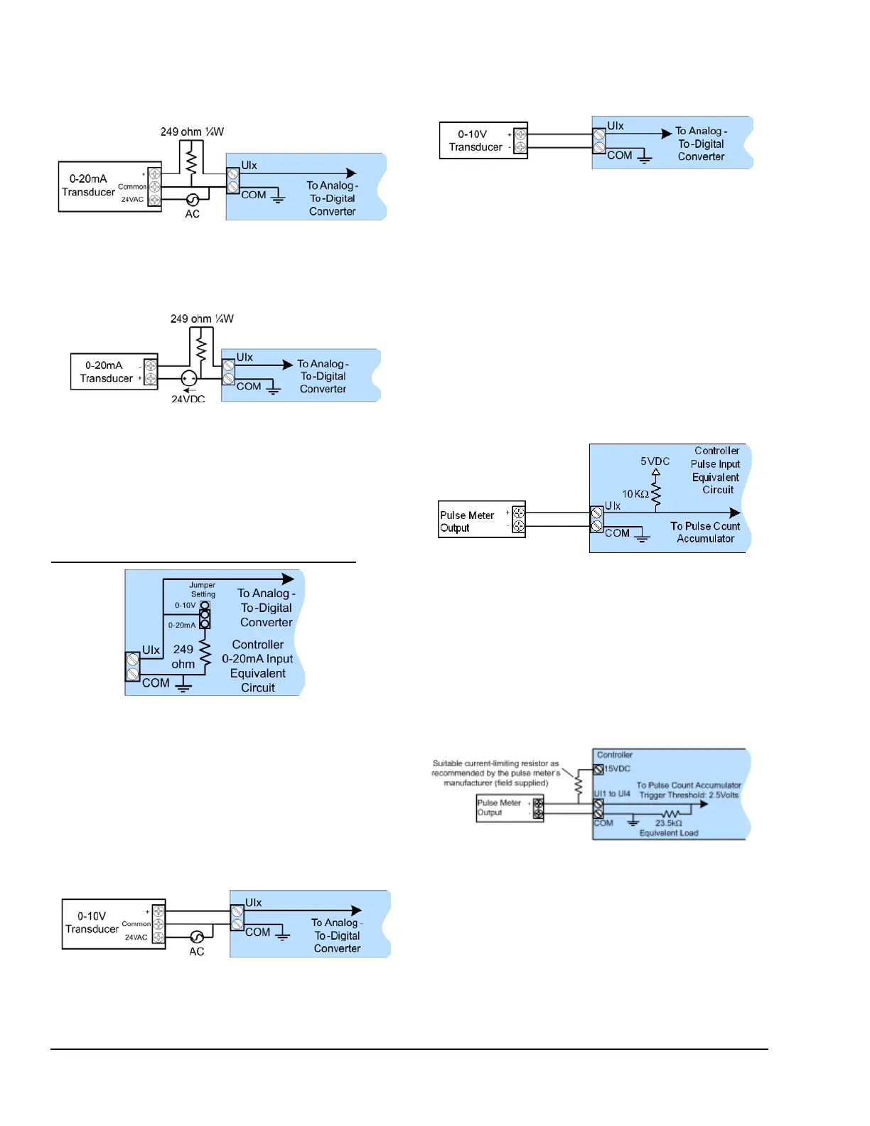
Use the Figure 14 configuration for a 3-wire, 0 to 20
mA transducer powered by an external 24 AC/DC
power supply.
Use the Figure 15 configuration for a transducer
powered by its own power source.
For the LN-PRG300-12, LN-PRG4x0-12, and
LN-PRG6x0-12 controllers, it is not necessary to
connect a 249 ohm resistor at the input as this resistor
is built-in to the controller. For these models, configure
the input jumper as follows. For jumper location, see
Configuration Jumper Location and Identification
.
Wiring Voltage Inputs
Voltage inputs have a range of 0 to 10 VDC or
0 to 5 VDC. Connect the voltage input according to
Figure 17 if you are using a 3-wire 0 to 10 V or 0 to 5 V
transducer.
Connect the voltage input according to Figure 18 if the
transducer is powered by its own power source.
Wiring Pulse Inputs
The input must be wired according to the requirements
of the connected pulse meter (for example, fast pulse
or slow pulse and internal or external supply type). See
Table 1.
Configure the Pulse Input Types in the software to
verify the pulse meter is powered correctly (set the
Internal/External Supply Type).
Connect the pulse input according to Figure 19 for a
pulse meter that can pull down a +5 VDC supply with a
10k ohm pull-up resistor (internal supply type).
When you use a pulse meter that requires more than
5 VDC to operate, you must use a Fast Pulse Input
type (Table 1). An external power supply is required to
operate the pulse meter. You may use the controller’s
built-in power supply as shown in Figure 20 or use an
external power source (from 6 VDC to 27 VDC
maximum — see Figure 21).
Figure 14: Current Input – 3-Wire Transducer,
Externally Powered
Figure 15: Current Input – Transducer with Its
Own Power Source
Figure 16: Equivalent Circuit for 0 to 20 mA
Current Input Showing the Jumper Setting for
the LN-PRG300-12, LN-PRG4x0-12, and
LN-PRG6x0-12 Controllers
Figure 17: Voltage Input – 3-Wire Transducer
Figure 18: Voltage Input – Transducer with Its
Own Power Source
Figure 19: All Pulse Input Types – Internal
Supply, 2-wire Pulse Meter
Figure 20: Fast Pulse Input Type - External
Supply, 2-wire Pulse Meter for LN-PRG300, LN-
PRG4x0-12, and LN-PRG6x0-12 Controllers