LN Series Free Programmable LN-PRGxxx-12 Controllers Installation Instructions 9
LN Series Communicating Sensors Wiring
The LN Communicating Sensors (LN-SVSEN-0 and
LN-SVSENH-0) are communicating room temperature
sensors with backlit displays and graphical menus.
Connect the LN-SVSENx-0 Sensor to the SUBNET
PORT modular connector of the controller with a
standard Category 5e Ethernet patch cable fitted with
RJ-45 connectors.
If you make your own patch cable, use category 5e
crimped with RJ-45 connectors either T568A or T568B.
Patch cable fitted with connectors supplied by Johnson
Controls are wired as T568B.
For more information on network topology and length,
cable type, setting the Subnet ID and more, refer to the
LN Series Communicating Sensors Installation
Instructions (LIT-12011795) and the L
ONWORKS
LN-Series Network Communication and Interface
Guide Technical Bulletin (LIT-12011253).
Output Wiring
Each controller has physical connections for digital
(triac) or universal outputs, depending on type and
model. These outputs are all software configurable.
Table 3 shows the controller outputs.
For jumper location, see Configuration Jumper
Location and Identification.
Note: Before you connect output equipment to the
controller, refer to the installation instructions from the
equipment manufacturer.
IMPORTANT: Do not crimp one connector as
T568A and the other connector as T568B on the
same cable.
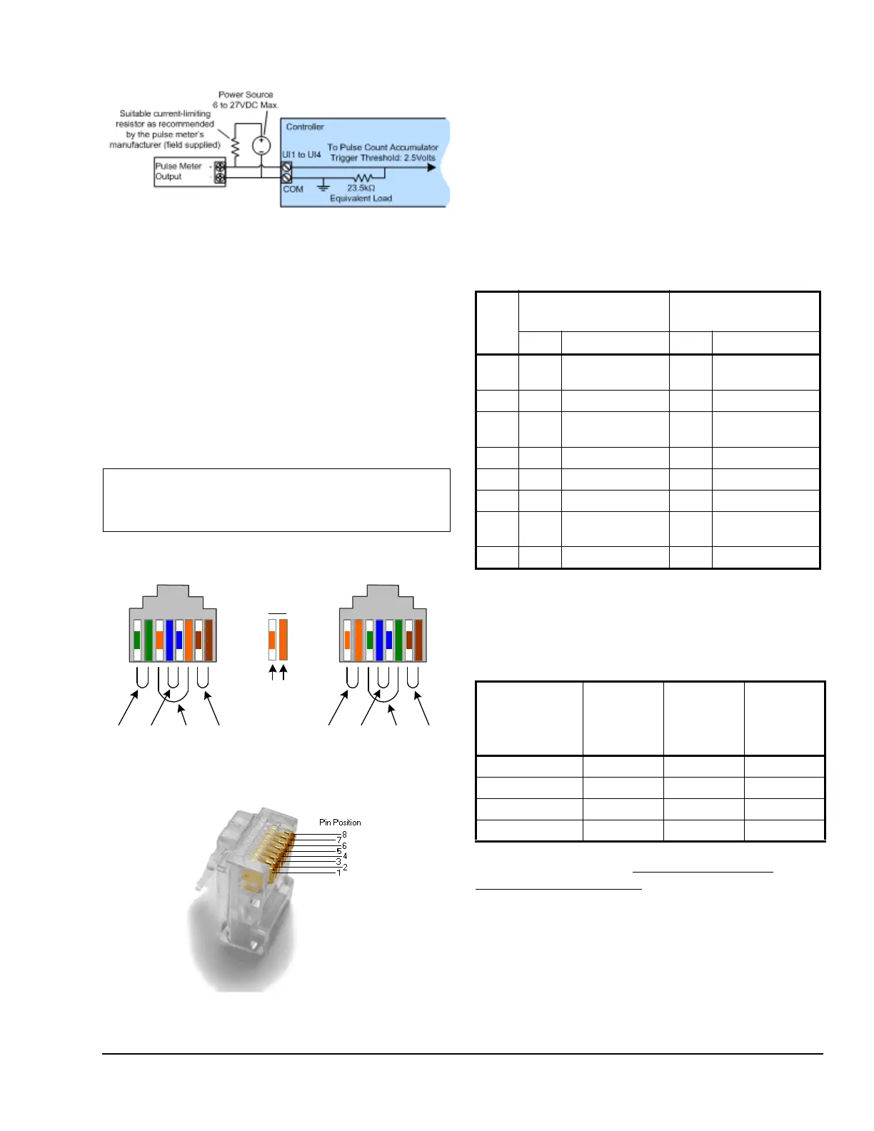
Figure 21: Fast Pulse Input Type – External
Supply, 2-wire Pulse Meter
Figure 22: T568A and T568B Crimp Wire
Sequence for an RJ-45 Connector
T568A T568B
Stripe Solid
1 2 345678 12345678
Pair 3 Pair 1Pair 2Pair 4 Pair 2 Pair 1Pair 3Pair 4
Key:
Figure 23: Pins on RJ-45 Jack Face
Table 2: T568A and T568B Terminations for RJ-45
Connector
Pin T568A (at both
cable ends)
T568A (at both
cable ends)
Pair Color Pair Color
1 3 white/green
stripe
2 white/orange
stripe
2 3 green solid 2 orange solid
3 2 white/orange
stripe
3 white/green
stripe
4 1 blue solid 1 blue solid
5 1 white/blue stripe 1 white/blue stripe
6 2 orange solid 3 green solid
7 4 white/brown
stripe
4white/brown
stripe
8 4 brown solid 4 brown solid
Table 3: Controller Output Support
Controller Digital
(Triac)
Outputs
Universal
Outputs
Jumper 0
to 10
VDC/0 to
20 mA
LN-PRG203-12 53no
LN-PRG300-12 0 8 yes
LN-PRG4x0-12 012yes
LN-PRG6x0-12 012yes