M Motor Actuators—M100C Series of Motor Actuators 3
LOAD END
10° (AX)
Direction of
Drive Rotation
COM to CCW Shorted
Drive Shaft
Y20A1-15
Keyway
Zero Reference
Position
Direction of Drive
Rotation COM to CW Shorted
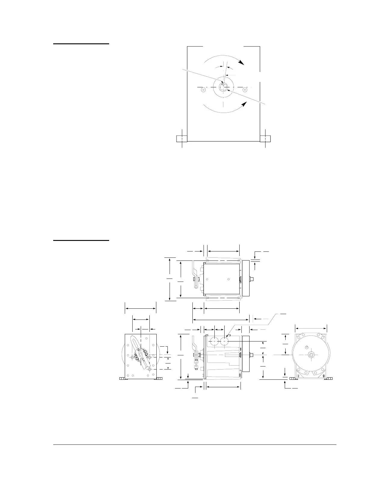
Figure 2: Direction of Rotation
All reference to the direction of rotation is when viewing the load end as
stamped on the actuator housing shown in Figure 2. From this view, the
Counterclockwise (CCW) limit is the zero reference.
The actuators are factory set at zero position which is 10 degree Clockwise
(CW) from vertical (see Figure 2) and for 90 degree clockwise travel.
When using Y20 linkage kits, each 15 degrees of actuator rotation results
in 0.1 inch (2.54 mm) of linear movement of the rack assembly.
1.69
43
4 Mounting Slots
.875
22.23
5.64
143
4.88
124
4.00
102
4.81
122
.56
14
.266
6.76
7.28
185
.45
12
1.50
38
1.31
33
3.31
84
4.65
118
.29
7
.38
10
.03
.76
5.81
148
1.75
45
.16
4
4.38
111
2.50
64
1.25
32
4 Holes
1.27
32
.97
25
.51
13
5.13
130
2.56
65
Top View
Load End
Auxiliary End
Side View
M100PB13.drw
Figure 3: M100 with Spring Return Dimensions
Figure 3 shows the dimensions for a standard M100 Series Motor
Actuator. Additional space is to be allowed for options such as a switch
kit (two inches additional length at auxiliary end).
Direction of
Rotation
Dimensions