M Motor Actuators—M100C Series of Motor Actuators 13
Calibration Procedures
M100C09
C
O
M
T
I
C
W
C
C
W
B
U
S
T
2
12 3
OFF
4
5
678
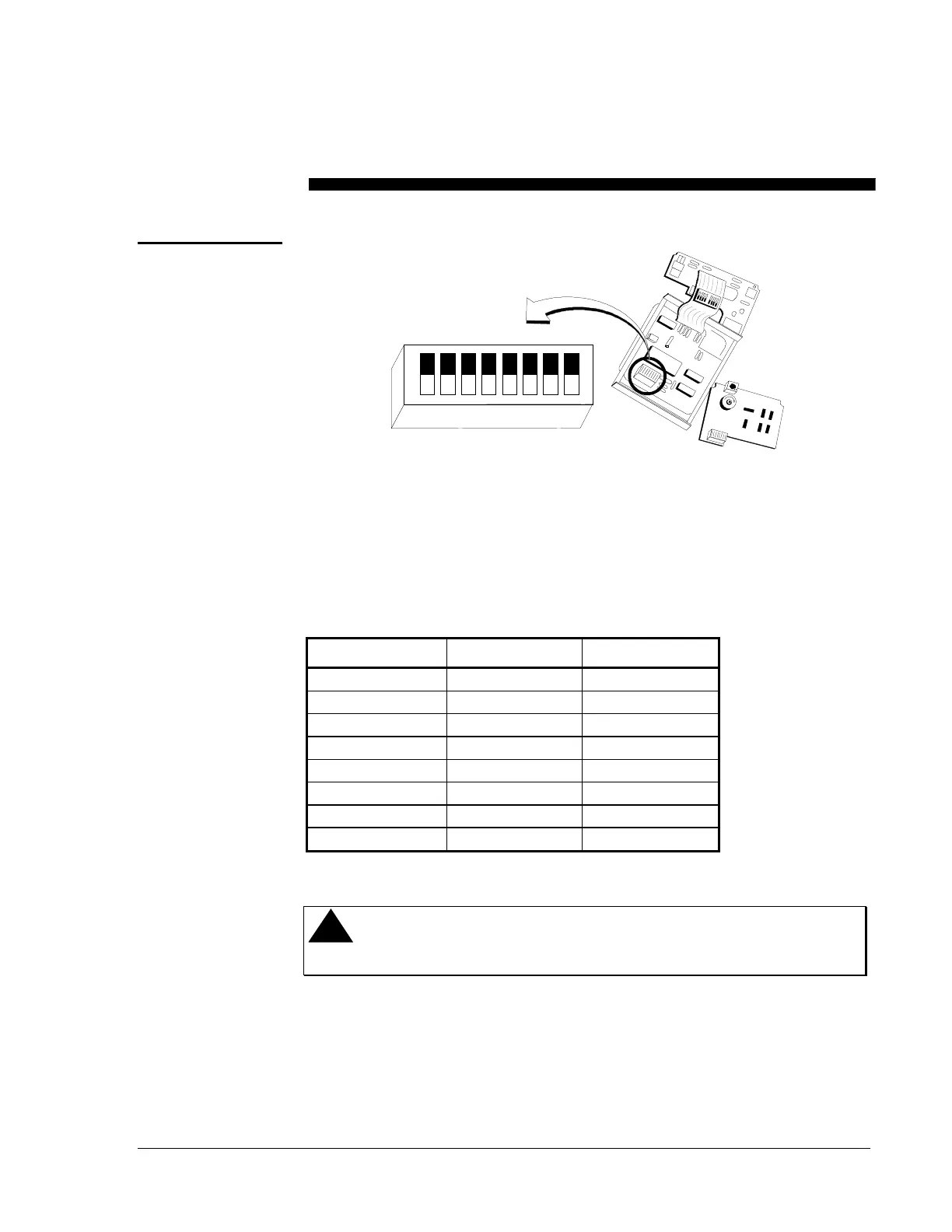
Figure 12: Digital Circuit Board
Make field adjustments using the 8-position DIP switch located on the
cover-mounted circuit board as shown in Figure 12. The position of these
switches specifies the operating parameters as shown in Table 4.
Table 4: Switch Settings
SWITCH NUMBER ON FUNCTION OFF FUNCTION
1
Master Slave
2
Linear S-curve
3
Direct Acting Reverse Acting
4
L1 Bus Zone Bus
5
Address Selection* Address Selection*
6
Address Selection* Address Selection*
7
Address Selection* Address Selection*
8
Address Selection* Address Selection*
*Refer to
Master/Slave
section (page 14) for complete address selection options.
!
CAUTION: Disconnect the electrical power supply before
attempting to adjust the switch settings.
Switch Settings