14 M Motor Actuators—M100C Series of Motor Actuators
When using multiple dampers and/or valves for similar functions, set the
actuators to respond to the same controller address. This requires that one
actuator be set as the master and the remaining actuators at that address be
set as slaves.
Note: Select only one master actuator for each address. Set single
actuators not involved in slaving as master except when connected
to the Metasys System.
Both the master and slave actuators receive commands from the controller,
but only the master actuator has continuous 2-way communication with
the controller. The slave actuators send response messages back to the
controller only if an error occurs at the slave.
Use Switch 1 to select whether the actuator will respond as a master or
slave. Positioning the switch to OFF sets the actuator for master operation
and positioning the switch ON sets the actuator for slave operation.
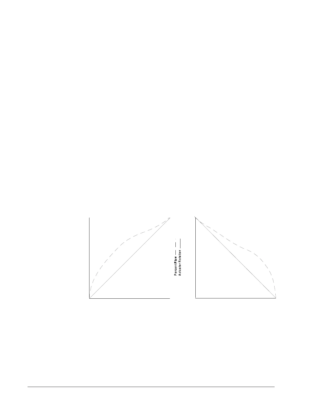
Valves and dampers with non-linear flow characteristics have the greatest
amount of flow occurring in the early portion of travel. The S-curve
switch setting allows the actuator to respond in a non-linear manner. The
actuators travel in relation to the input command is smaller during the
initial 20% of command, increases during the mid 60% of command, and
then decreases during the final 20% of the command.
Figure 13: Linear Characteristics
Master/Slave
Linear/S-Curve Flow
Characteristics
0%
0%
100%
Controller Command
100%
20%
40%
60%
80%
20%
40%
60%
80%
0%
0%
100%
Controller Command
100%
20%
40%
60%
80%
20%
40%
60%
80%
m100C09