M Motor Actuators—M100C Series of Motor Actuators 15
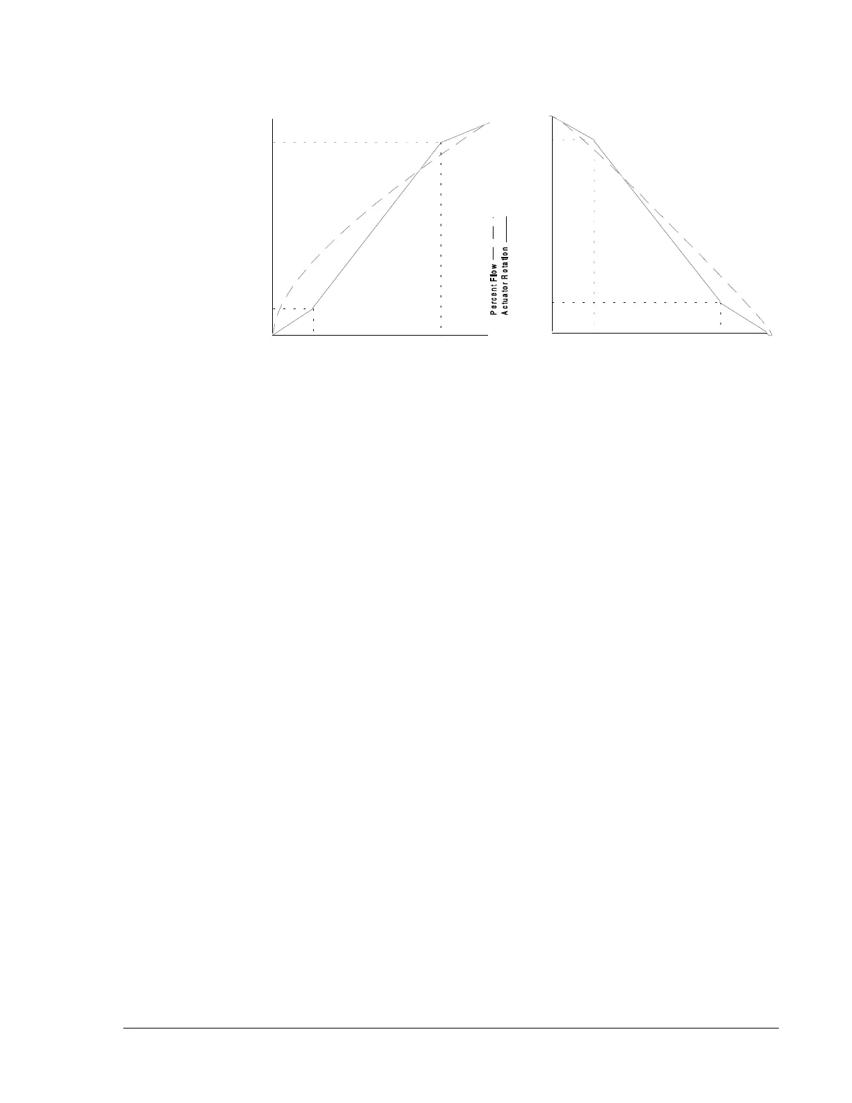
Figure 14: S-Curve Characteristics
Use Switch 2 to select the response. Positioning the switch to OFF sets
the actuator for linear operation as shown in Figure 13. Positioning the
switch to ON sets the actuator for S-curve operation as shown in
Figure 14.
The M100C is factory calibrated for direct action where a 0 to 100%
command input will provide a CW shaft output (0% = full CCW and
100% = full CW) as viewed from the load end. Switch 3 is set to OFF.
Reverse action where a 0 to 100% command input will provide a CCW
shaft output (100% = full CCW and 0% = full CW) as viewed from the
load end is field selected. Change Switch 3 to ON.
C500 Controllers use the L1 Bus. AHU Controllers use the Zone Bus. Set
Switch 4 to the OFF position to allow the actuator to communicate with a
C500 Controller and to ON to communicate with an AHU Controller.
An address is a numeric code that precedes a controller’s command to a
controlled device. The controlled device will respond only to a command
preceded by its assigned address code number.
The positioning of Switches 5, 6, 7, and 8 provides address information to
the controller. The switches are each positioned such that the sum of their
individual values provides the desired address value.
Configure multiple actuators with a separate address when each one
performs a different function. When they all perform the same function,
set one unit as the master, with the remaining units on that address set as
slaves.
0%
0%
100%
Controller Command
100%
20%
40%
60%
80%
20%
40%
60%
80%
20% Command = 10%
Actuator Rotation
80% Command = 90%
Actuator Rotation
0%
0%
100%
Controller Command
100%
20%
40%
60%
80%
20%
40%
60%
80%
20% Command = 90%
Actuator Rotation
80% Command= 10%
Actuator Rotation
M100C10
Direct/Reverse
Action
L1/Zone Bus
Address Selection