M9203-Bxx-2(Z) Series On/Off Electric Spring Return Actuators Installation Guide
7
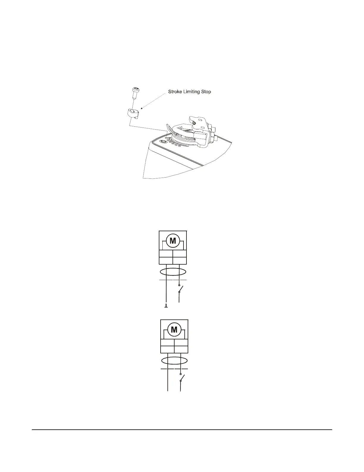
2. Position the stroke-limiting stop in the serrated slot with its leading edge at the scale position matching the
desired stroke.
3. The product label marks hole positions for the M3-0.5 x 8 mm self-tapping screw provided with the adjustable
stop kit. Drive the screw through the slot in the adjustable stop and into the actuator face over a marked hole
position. (See Figure 8.)
Note: The minimum rotation range is 35°.
Wiring
See Figure 9 and Figure 10 to wire the applicable M9203-Bxx-2(Z) Series model.
Figure 8: Limiting Rotation Range
AC 85...264 V 50/60 Hz
L1N
WHT BLK
2
1
AC 24 V 50/60
DC 24 V
RED
BLK
2
1
+
-
~
F
I
G
:
M
9
2
0
3
B
x
x
2
_
w
i
r
i
n
g

 Loading...


