I/O terminal blocks, ratings, and
requirements
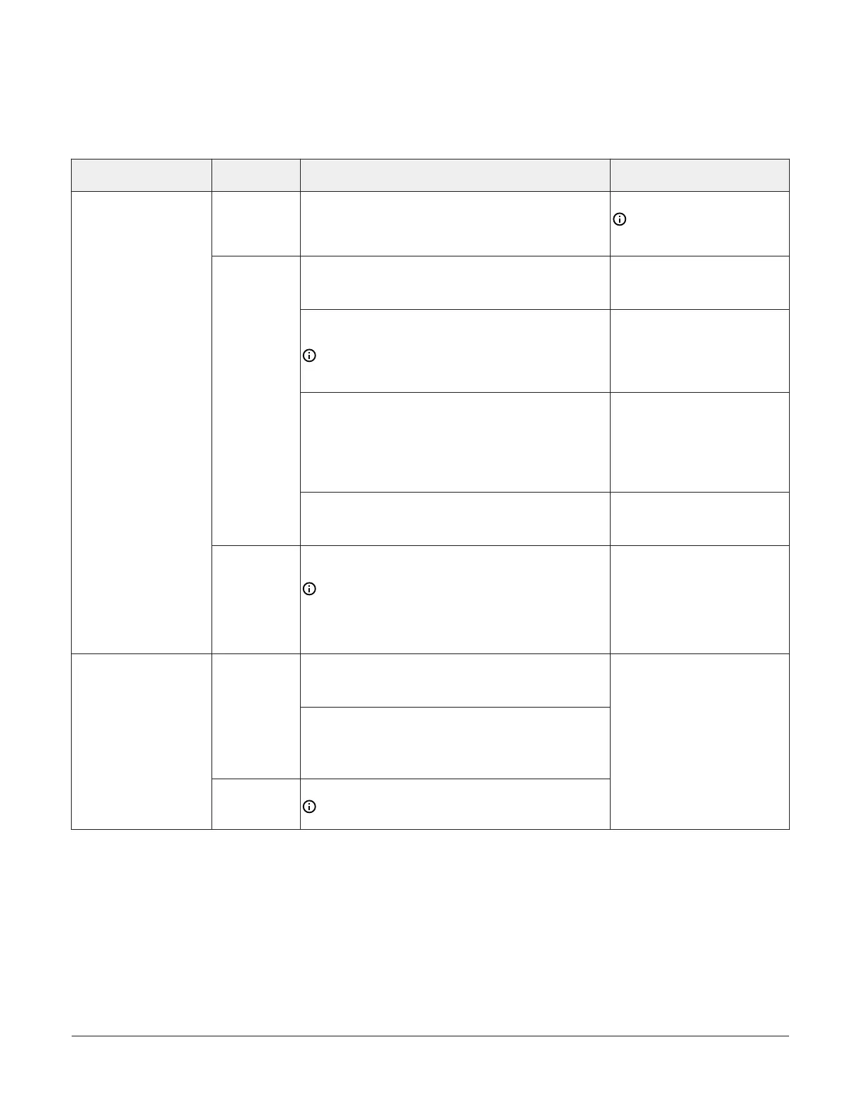
Table 3: I/O terminal blocks, functions, ratings, requirements, and cables
Terminal block label Terminal label Function, ratings, requirements
Determine wire size and
maximum cable length
+15 V
15 VDC Power Source for active (3-wire) input devices
connected to the Universal INn terminals.
Provides 100 mA total current
Same as (Universal) INn
Note: Use 3-wire cable for
devices that source power
from the +15V terminal.
Analog Input - Voltage Mode (0–10 VDC)
10 VDC maximum input voltage
Internal 75kΩ pull-down
See Guideline A in Table .
Analog Input - Current Mode (4–20 mA)
Internal 100 Ω load impedance. See .
Note: A current loop fail-safe jumper must be in
the Enable position to maintain a closed 4 to 20 mA
current loop. See .
See Guideline B in Table .
Analog Input - Resistive Mode (60–600kΩ )
Internal 12 V. 15k Ω pull-up
Qualified Sensors: 0–2kΩ potentiometer, RTD (1k Nickel
[ Johnson Controls sensor], 1k Platinum, and A99B Silicon
Temperature Sensor) Negative Temperature Coefficient
(NTC) Sensor
See Guideline A in Table .
INn
Binary Input - Dry Contact Maintained Mode
1 second minimum pulse width
Internal 12 V. 15kΩ pull-up
See Guideline A in Table .
UNIVERSAL
(Inputs)
ICOMn
Universal Input Common for all Universal Input
terminals
Note: All Universal ICOMn terminals share a
common, which is isolated from all other commons,
except the SA bus common. One common screw
terminal point is provided for every two input screw
terminal points.
Same as (Universal) INn
Binary Input - Dry Contact Maintained Mode
0.01 second minimum pulse width
Internal 18 V. 3k Ω pull-up
INn
Binary Input - Pulse Counter/Accumulator Mode
0.01 second minimum pulse width
(50 Hz at 50% duty cycle)
Internal 18 V. 3kΩ pull-up
BINARY
(Inputs)
ICOMn
Binary Input Common for all Binary Input (IN) terminals
Note: All Binary ICOMn terminals share a common,
which is isolated from all other commons.
See Guideline A in Table .
FAC4911 Advanced Application Field Equipment Controller Installation Guide8