Terminal wiring and cable length guidelines
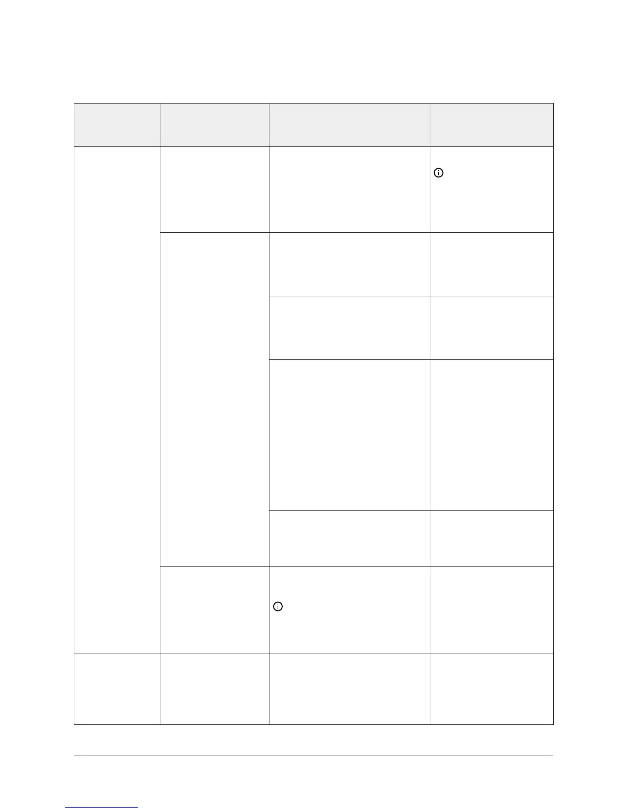
Table 12: Terminal wiring
Terminal block
label
Terminal labels Function, ratings, and
requirements
Determine wire size
and maximum cable
length
+15 V 15 VDC Power Source for
active (3-wire) input devices
connected to the Universal INn
terminals.
Provides 100 mA total current.
Same as Universal INn.
Note: Use 3-wire
cable for devices
that source power
from the +15 V
terminal.
Analog Input - Voltage Mode
(0–10 VDC)
10 VDC maximum input voltage
Internal 75k Ohms Pulldown.
See Guideline A in Table
13.
Analog Input - Current Mode
(4–20 mA)
Internal 100 Ohms load
Impedance.
See Guideline B in Table
13.
Analog Input - Resistive Mode
(0–600k Ohms)
Internal 12 V, 15k Ohms pull up.
Qualified Sensors: 0–2k
potentiometer, RTD (1k Nickel
[Johnson Controls sensor], 1k
Platinum, and A99B Silicon
Temperature Sensor) NTC
Sensor (10k Type L, 10k JCI Type
II, 2.252k Type II).
See Guideline A in Table
13.
INn
Binary Input - Dry Contact
Maintained Mode1 second
minimum pulse width Internal
12 V, 15k Ohms pull up.
See Guideline A in Table
13.
UNIVERSAL
(Inputs)
ICOMn Universal Input Common for
all Universal IN terminals
Note: All Universal
ICOMn terminals share a
common, which is isolated
from all other commons.
Same as (Universal)
INn.
BINARY
(Inputs)
INn Binary Input - Dry Contact
Maintained Mode
0.01 second min. pulse width.
Internal 18 V, 3k Ohms pull up.
See Guideline A in Table
13.
21NCE25 Installation Instructions

 Loading...


