Table 13: Cable length guidelines for recommended wire sizes
Guideline Wire size/gauge and type Maximum cable
length and type
Assumptions
C See Figure 13 to select wire size/
gauge. Use stranded copper wire.
See Figure 13 to
determine cable
length. Use twisted
wire cable.
N/A
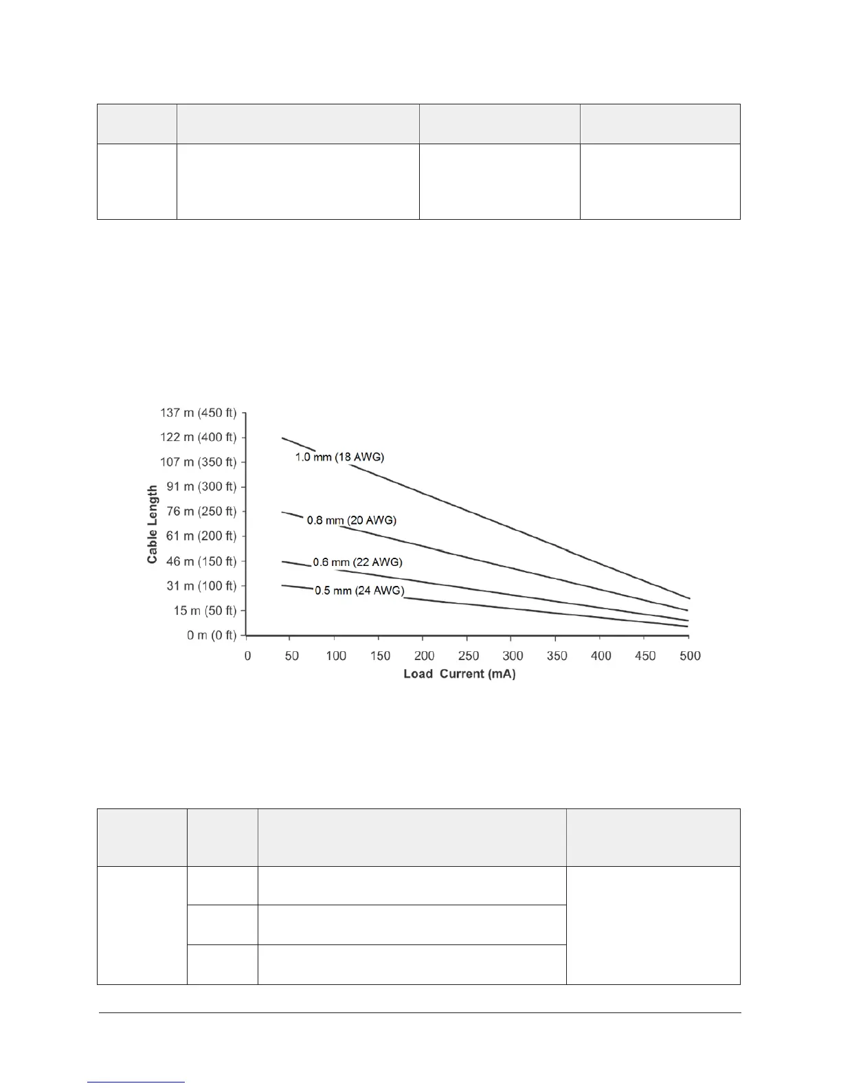
Maximum cable length versus load current
In most cases inputs/outputs with cables less than 30 m (100 ft) do not require an offset in the
software setup. Cable runs over 30 m (100 ft) may require an offset in the input/output software
setup.
Use Figure 13 to estimate the maximum cable length relative to the wire size and the load current
(in mA) when wiring inputs and outputs.
Figure 13: Maximum wire length by current and wire size
Communications Bus and supply terminal blocks, functions,
ratings, requirements, and cables
Table 14: Communications bus and supply terminal blocks, functions, ratings, requirements, and
cables
Terminal
block/port
label
Terminal
labels
Function, electrical ratings/requirements Recommended cable
type
+
_
FC Bus Communications
COM Signal Reference (Common) for bus
communications
FC BUS
SHLD Isolated terminal (optional shield drain
connection)
0.6 mm (22 AWG)
stranded, 3-wire
twisted, shielded cable
recommended
NCE25 Installation Instructions26

 Loading...


