Issue Date August 8, 2002
© 2002Johnson Controls, Inc.
1
Part No. 24-8980-2, Rev. A www.johnsoncontrols.com
Code No. LIT-6363155
T
ECHNICAL
B
ULLETIN
TEC1100 Series Thermostat
In this document, Building Automation System (BAS) is a generic term
that refers to the Metasys® Network (Network Control Module [NCM] or
N30 series), Companion, and Facilitator® supervisory systems. When you
refer to system specific applications, use the specific system names.
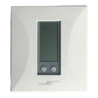
The TEC1100 Series includes three nonprogrammable models:
single-stage (TEC1101), heat pump (TEC1102), and multistage
(TEC1103). The applications include furnace, air conditioner, heat pump,
and rooftop units. The TEC1100 incorporates fuzzy logic for precise
control in a thermostat type package.
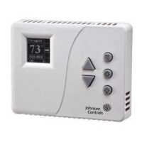
All TEC1100s have Metasys N2 communication capability. This
communication allows the user to view and adjust parameters from a
remote workstation. It also provides information, such as outdoor air
temperature, to the TEC1100 units on the bus. The thermostat is easy to
operate and normally displays room temperature and mode of operation
using Cooling ( ) or Heating ( ) icons. When there is a call for cooling,
the Snowflake icon ( ) blinks. Likewise, during a call for heating, the
Flame icon ( ) blinks. When the temperature is satisfied, neither icon
blinks. In the Auto mode, both icons ( ) appear continuously when
satisfied. Light-Emitting Diodes (LEDs) on the top of TEC1102/1103
models use Binary Inputs (BIs) to indicate a clogged filter and external
service. A unique temperature alarm (BI 2) indicates that the zone
temperature has not been satisfied in 45 minutes.
Introduction
Description