• Use copper conductors only. Make all wiring
in accordance with local, national, and
regional regulations.
• The network engine is a low-voltage (<30
VAC) device. Do not exceed the network
engine electrical ratings. Applying high
voltage to the network engine may result in
permanent damage to the network engine
and void any warranties.
• Do not remove the terminal block keys. The
terminal block plugs and the terminal sockets
are keyed to fit together in the correct
configuration only.
• Prevent any static electric discharge to the
network engine. Static electric discharge can
damage the network engine and void any
warranties.
Follow these guidelines when wiring the network
engine:
• Route the supply power wires and communication
cables at least 50 mm (2 in.) away from the vent
slots in the sides of the network engine housing.
• Provide slack in the wires and cables. Keep cables
routed neatly around the network engine to
promote good ventilation, LED visibility, and ease
of service.
• Ensure that the building automation network
wiring meets the specifications, rules,
and guidelines as outlined in the Wiring
considerations and guidelines for network
integrations section. The network engine does not
require an earth ground connection.
• Follow the transformer manufacturer’s
instructions and the project installation drawings.
Power supply wire colors may be different on
transformers not manufactured by Johnson
Controls.
• While connecting network devices to 24 VAC
power, make sure that transformer phasing is
uniform across all devices. Powering network
devices with uniform 24 VAC supply power
phasing reduces noise, interference, and ground
loop problems.
Connecting MS/TP or N2 bus devices
To connect devices to the MS/TP Field Controller (FC)
Bus or N2 Bus, complete the following steps:
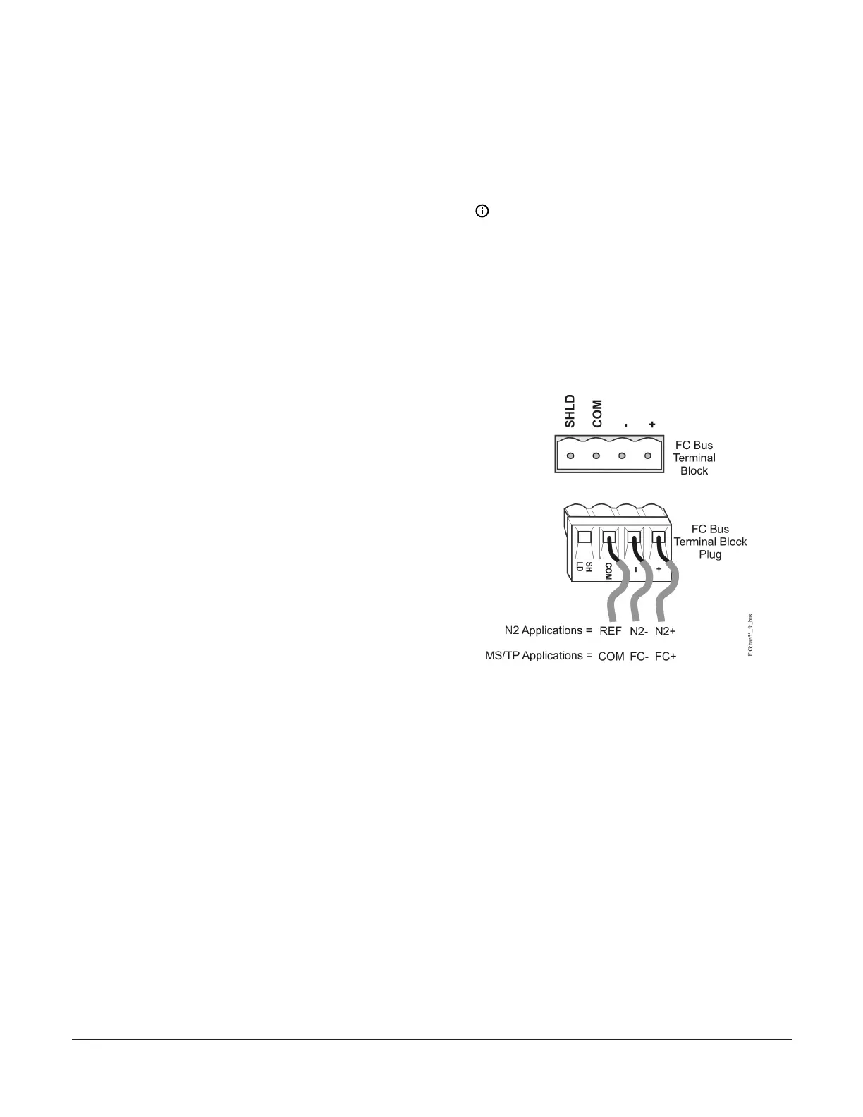
1. Connect the 3-wire bus cable to the removable
blue 4-pin terminal block labeled FC-A as shown
in Figure 8.
Note: The FC-A and FC-B terminals can
accept either the MS/TP FC Bus or the N2
Bus, but not a mixture of both on the same
trunk. If you want to integrate both the
MS/TP Bus and the N2 Bus, select one FC
terminal for MS/TP FC Bus use and the
other for N2 Bus use.
Figure 8: FC Bus terminal block and wiring
connections
2. To add additional field devices, wire from one
device to the next as shown in Figure 9. Do not
connect more than two wires to each terminal
to ensure that a daisy chain configuration is
used.
NAE55/NIE55 Installation Guide 7