A421 Series Standard Electronic Temperature Controls Installation Instructions
6
Replacing an A419 Control with an A421 Control:
Terminal Locations and Labels
The A421 Series Electronic Temperature Controls are
the next generation of the A419 Series Electronic
Temperature Controls.
If you need to replace an A419 control with an A421
control, be sure to note that wiring terminals on the TB1
and TB2 terminal blocks on A421 controls are in
different positions and have different terminal labels
from the wiring terminals on the A419 controls. Table 3
provides a cross-reference for matching the terminal
labels on A419 controls to the terminal labels on A421
controls.
Note: The low-voltage signal terminals on the TB3
terminal block are labeled the same on both A419
controls and A421 controls.
See Figure 4 for terminal block and terminal positions
on the A421 control.
Setup and Adjustments
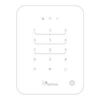
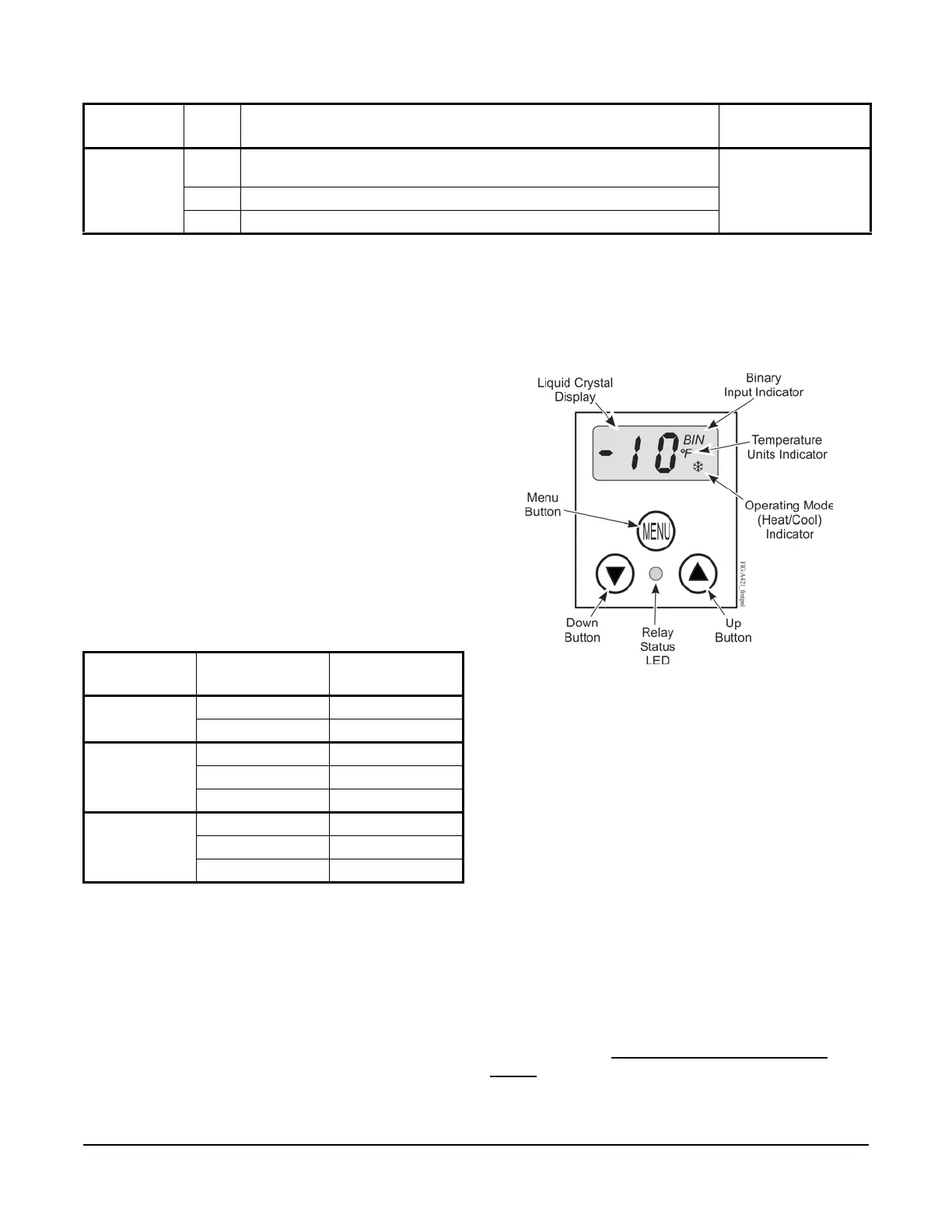
Front Panel
The front panel of the A421 Series Electronic
Temperature Control has a simple LCD and a
three-button user interface (Figure 5).
Liquid Crystal Display
The A421 Series Control has a backlit LCD screen
(Figure 5). The LCD brightness is adjustable. During
normal operation, the LCD displays the Main screen,
which provides following information:
• the temperature sensed at the A99 sensor
• the selected temperature units (°F or °C)
• the mode of operation (Flame = Heating mode,
Snowflake = Cooling mode)
• Binary Input status (BIN) when a (user-supplied)
binary input (switch) is connected and closed to
enable the temperature setback feature.
During setup and adjustment, the LCD displays the
parameter code screens and the parameter value
screens. See the A421 Control Parameter Setup
Menus on page 9 for more information.
TB3 BIN Detects a switch closure between the BIN and COM terminals and enables
the selected temperature setback (tSb) value.
22 AWG (0.34 mm
2
)
stranded, shielded
cable recommended
COM Connects low-voltage common from the sensor and binary input.
SEN Connects low-voltage input signal wire from control sensors.
Table 2: A421 Control Wiring Terminals and Wire Size Information (Part 2 of 2)
Terminal
Block
Label Description, Function, and Requirements Recommended
Wire Sizes
Table 3: A419 and A421 Wiring Terminal Labels
Terminal
Block
A419 Terminal
Label
A421 Terminal
Label
TB1
(24 VAC)
T1 LN
T2 24V
TB1
(120/240 VAC)
120 120V
240 240V
AC COM LN
TB2
(All Voltages)
CLC
NO LNO
NC LNC
Figure 5: A421 Control Front Panel with LCD
and Three-Button User Interface

 Loading...