System 450™ Series Modular Control Systems with Standard Control Modules Technical Bulletin56
Setting Up Outputs That Reference a P 110 Sensor
The P 110 Sensor Type can monitor negative pressure down to 20 inHg (-10 psi).
When referencing a P 110 sensor, System 450 displays negative pressure values in
inHg on the Main and System Status screens. But when you set up an output that
references a P 110 sensor and the setup value is a negative pressure value, you
must select the pressure value in negative psi (not inHg).
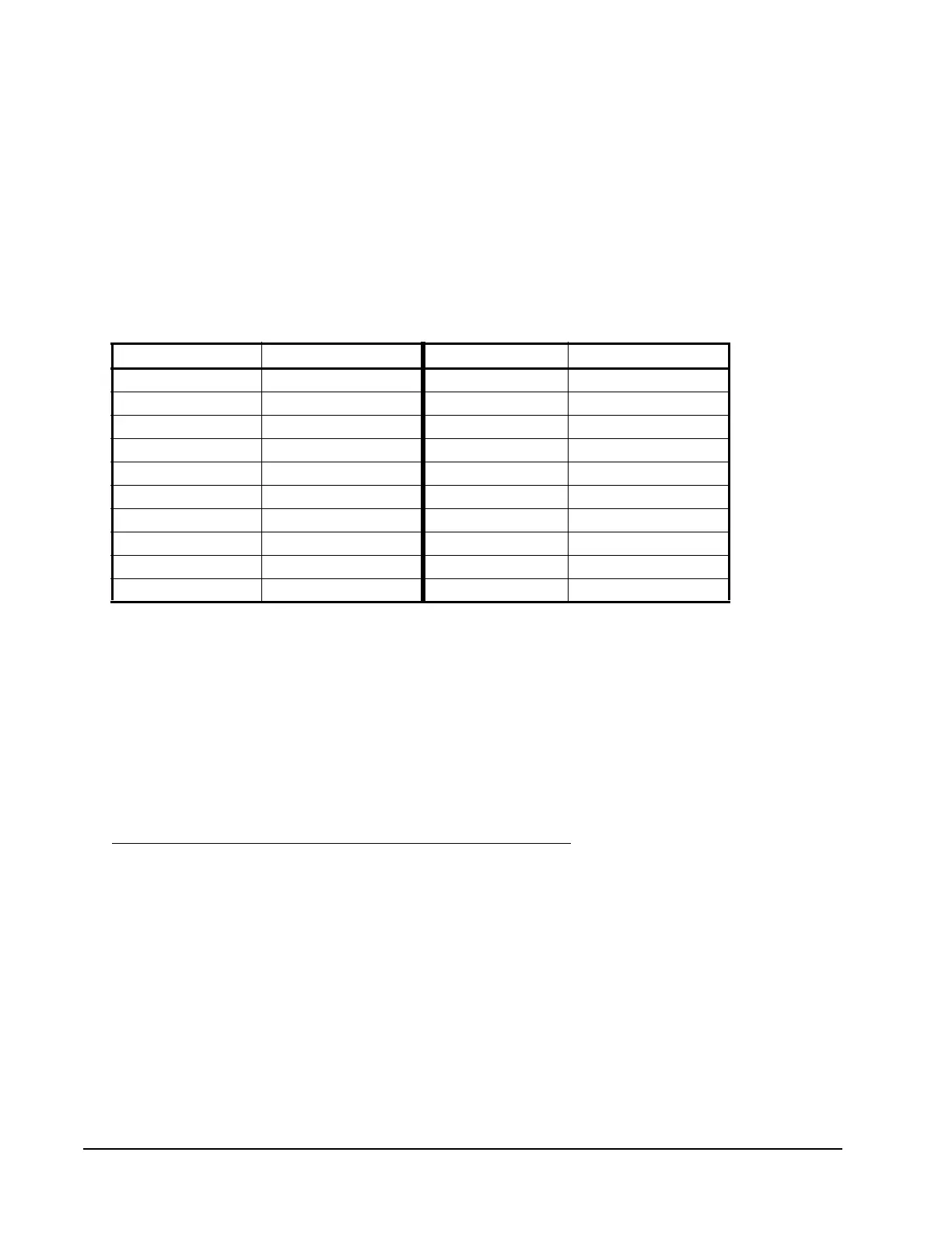
Use Table 7 to determine the negative PSI setup value that corresponds to your
inHg target value. For example, if you want a relay output to go off when the
sensed pressure reaches 7 inHg, you select the value -3.5 (psi) in the output’s Relay
OFF Selection screen.
When an output is set up for Differential Control and references the P 110 Sensor
Type (Sn-1 and Sn-2 are both P 110 Sensor Type), the sensed negative pressure
values displayed in the Main screen for differential pressure status (dIFP) are
displayed as negative psi values, not inHg values.
Determining the Integration Constant for an Analog Output
The default Integration Constant (I-C) setting for analog outputs is 0 (zero) or no
integration constant. An I-C setting of 0 provides a proportional-only analog
signal. Many applications do not require you to change this default setting. See
Proportional Plus Integral Control and Integration Constants on page 23 for more
information.
If you want to apply proportional plus integral to a control loop in your controlled
system, here are two methods of determining the best I-C setting for the analog
output that controls the loop.
Note: Both of the following methods for determining an I-C setting require you to
install, set up, and operate the control loop in your controlled system under
a variety of typical load conditions and observe the response to load
changes and different I-C settings.
Table 7: inHg Target Values and Equivalent psi Setup Values
inHg Value psi Setup Value inHg Value psi Setup Value
1 -0.5 11 -5.5
2 -1.0 12 -6.0
3 -1.5 13 -6.5
4 -2.0 14 -7.0
5 -2.5 15 -7.5
6 -3.0 16 -8.0
7 -3.5 17 -8.5
8 -4.0 18 -9.0
9 -4.5 19 -9.5
10 -5.0 20 -10.0

 Loading...


