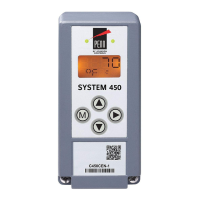
System 450 Glossary of Terms
Term Definition
°C Degrees Celsius (°C) appears in the Main (sensor status) screens, along
with the current sensed temperature value, when a Celsius temperature
sensor is set up in your control system. °C also designates a Sensor Type
that is available when you set up the sensors in the Sensor Setup screens.
See Accessing and Navigating the User Interface on page 42 and System
450 Compatible Sensors and Transducers on page 15 for more
information.
°F Degrees Fahrenheit (°F) appears in the Main (sensor status) screens, along
with the current sensed temperature value, when a Fahrenheit temperature
sensor is set up in your control system. °F also designates a Sensor Type
that is available when you set up the sensors in the Sensor Setup screens.
See Accessing and Navigating the User Interface on page 42 and System
450 Compatible Sensors and Transducers on page 15 for more
information.
Active Sensors Three-wire input sensors that require a low-voltage power source to
generate their input signal. Active sensors are hard-wired to one of the
sensor input terminals (Sn1, Sn2, or Sn3), a Common terminal (C), and
either the 24 V or 5 V power terminal on the low-voltage terminal block on
the control module. All of the System 450 compatible pressure transducers
and humidity sensors are active sensors. You must set the associated
active/passive jumper or DIP switch to the active position for each active
sensor that is hard wired to the sensor terminals. See Active and Passive
Sensors on page 17 for more information.
Analog Output System 450 provides self-selecting 0 to 10 VDC signal or 4 to 20 mA
signal analog outputs. The analog outputs can be set up to provide a wide
variety of direct and reverse acting proportional control applications,
including multi-stage control and proportional plus integral control.
Analog outputs are identified in the System 450 UI as OUTA in the Output
Setup Start screens and with a percent signal strength and control ramp
icon in the System Status screens. See Analog Outputs
on page 20, Setting
up an Analog Output on page 50, and Viewing the System Status Screens
on page 42 for more information.
bAR bAR appears in the Main (sensor status) screens along with the current
sensed pressure value, when your control system uses one or more
pressure transducers with P 8, P 15, P 30, or P 50 Sensor Types. Bar is an
SI (International System) unit of measurement for the pressure value
displayed in the Main screens. One bar is equal to approximately one
atmosphere of pressure, 14.5 psi, and 100 kPa. See System 450 Sensors
and Transducers for Standard Control Modules on page 16 for more
information.

 Loading...