VFD68 Variable Frequency Drives (575 VAC)
12
• Prevent VFD-generated EMI from causing functional problems.
- Do not run the low-voltage signal cables and the high-voltage power cables in parallel with each other,
and do not bundle them together.
- Run low-voltage signal cables as far away as possible from high-voltage power cables.
- Use shielded cables for the low-voltage signal cables. Connect the sensor cable shield at only one
point and that one point is the same terminal as the sensor's common wire.
- Install a ferrite core on the signal cable (for example, ZCAT3035-1330 TDK).
Terminal Screw Torque Specifications
Tighten the terminal screw to the specified torque. Over-tightening the terminal screws may damage the
terminal blocks and screw threads. Loose terminal screw connections can result in a short circuit or
malfunction.
Branch Circuit Protection
Integral solid-state short circuit protection does not provide branch circuit protection. The installer must provide
branch circuit protection in accordance with the National Electrical Code for the U.S. or the Canadian Electrical
Code for Canada and any additional codes.
As specified, UL Class T fuses or any faster acting fuse with the appropriate rating or Listed UL 489 Molded
Case Circuit Breaker (MCCB) must be employed in accordance with Table 7.
Short Circuit Ratings
The VFD68 Drives meet the requirements for their respective rating categories (Table 8).
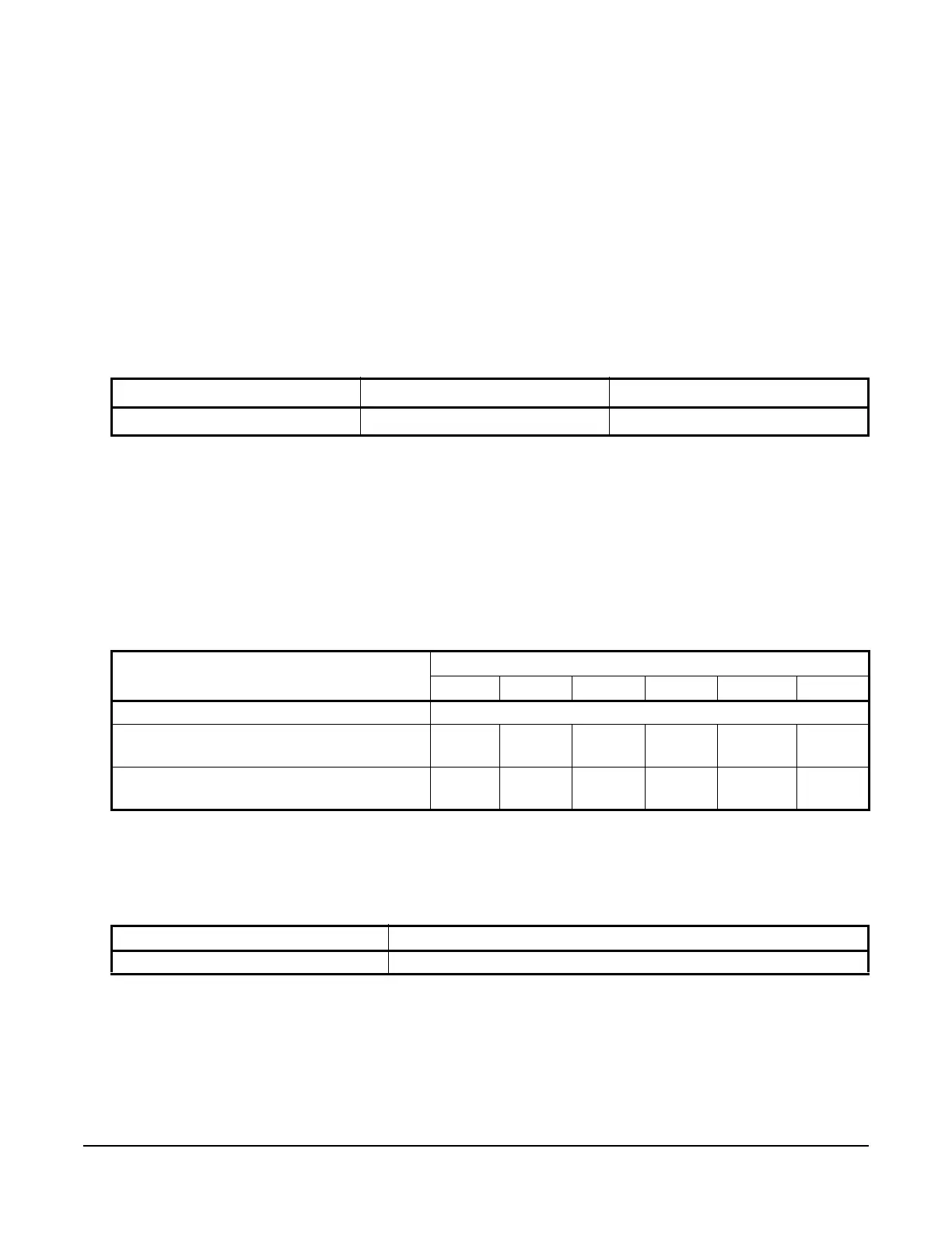
Table 6: Torque Specifications for VFD68Dxx Drives
Rated Capacity, kW (HP)
Terminal Screw Size
1
1. The terminal screw size indicates the terminal size for R/L1, S/L2, T/L3, U, V, W, PR, P/+, N/-, P1 and a screw for
earthing (grounding).
Tightening Torque, N•m (lb•in.)
0.75–7.5 (1–10)
M4 1 (8.85)
Table 7: VFD68Dxx Drives Electrical Ratings
VFD68 575 VAC kW (HP)
0.75 (1) 1.5 (2) 2.2 (3) 3.7 (5) 5.5 (7.5) 7.5 (10)
Rated fuse voltage (V) 575 V or more
Fuse Maximum allowable rating (A)
(without power factor improving reactor)
1
1. Maximum allowable rating by US National Electrical Code. Exact size must be chosen for each installation.
6 A 10 A 15 A 20 A 30 A 40 A
Molded case circuit breaker (MCCB)
Maximum allowable rating (A)
1
5 A 10 A 15 A 20 A 30 A 30 A
Table 8: VFD68 Drives Short Circuit Ratings
Rating Category Suitable for use in a circuit capable of delivering not more than
VFD68Dxx Drives (575 VAC Class) 100 kA rms symmetrical amperes, 600 V maximum