VFD68 Variable Frequency Drives (575 VAC)
22
VFD68Dxx Drive Parameters
You can use the default parameter setting with the P499RxP-107C Transducer and R410a refrigerant within a
range of operation that depends on the specific model of P499 Transducer selected. All other applications
require some parameter changes and may require different transducers.
PU Lit to indicate the PU operation mode
EXT Lit to indicate the external operation mode
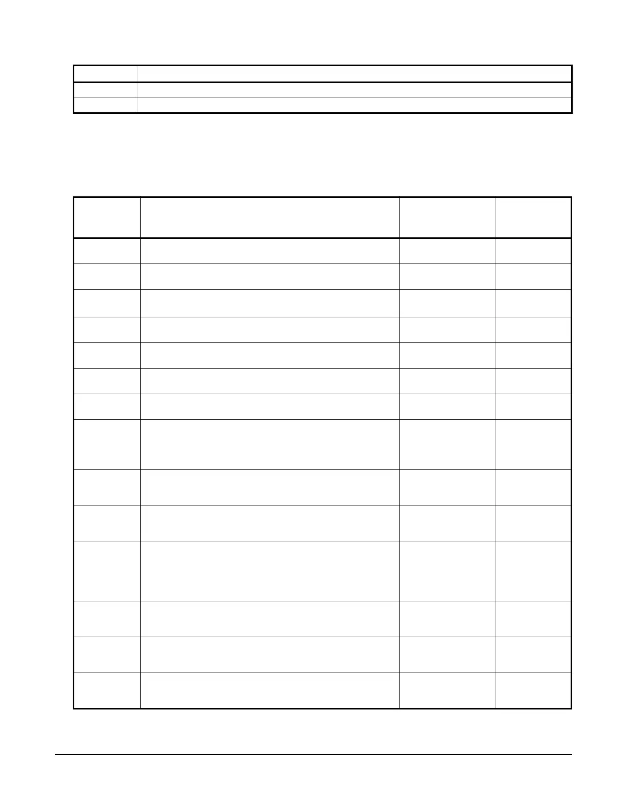
Table 16: Parameter Descriptions for VFD68Dxx Drives (Part 1 of 2)
Parameter
Indication
on Monitor
Description Settings Default
Setting
P. 0 Torque Boost: Defines the voltage (% total V) applied to the
motor when the drive starts the motor at 0 Hz.
0–30% 4% or 3%
P. 1 Maximum Frequency: Defines the maximum speed of the
motor in your application. See Figure 14.
0–120 Hz 60 Hz
P. 2 Minimum Frequency: Defines the minimum speed of the
motor in your application.
1
See Figure 14.
0–120 Hz 12.5 Hz
P. 3 Base Frequency: Set parameter to the rated frequency [Hz]
on motor rating plate.
0–400 Hz 60 Hz
P. 7 Acceleration Time: Defines the time required to accelerate
from stop (0 Hz) to full rated RPM (60 Hz).
0–3600 seconds 15 seconds
P. 8 Deceleration Time: Defines the time required to decelerate
from full rated RPM (60 Hz) to stop (0 Hz).
0–3600 seconds 15 seconds
P. 9 Motor Rated Current: Set parameter to the rated FLA on
motor rating plate.
0–500 A Rated VFD68
Output
P. 19 VFD Output Voltage: Defines the maximum output voltage
relative to the drive supply voltage.
2
• 9999: the maximum output voltage is the same as the
drive power supply voltage
0–1000V, 9999 9999
P. 22 Stall Prevention Output Current Level: Defines the current
level (as a % of motor FLA) at which the drive begins to
adjust the output frequency (Hz) to reduce the output current.
0–200% 150%
P. 31 Frequency Jump 1A: Frequency Jump parameters (P. 31
and P. 32) are used to set the low speed behavior of the
drive. This parameter typically remains at 0 Hz
0–400 Hz, 9999 0 Hz
P. 32 Frequency Jump 1B: Maximum frequency to skip over to
avoid very low fan airflow and unnecessary motor
overheating. (9999: frequency jump not enabled)
1
Note: Ensure that this is set equal to P. 90 2 (screen a) and
P.904 (screen a).
0–400 Hz, 9999 12.5 Hz
P. 33 Frequency Jump 2A: To avoid resonance noise caused by
natural frequency of mechanical system, enter frequency just
below noisy frequency 2.
0 to 400 Hz, 9999 9999
P. 34 Frequency Jump 2B: To avoid resonance noise caused by
natural frequency of mechanical system, enter frequency just
above noisy frequency 2.
0 to 400 Hz, 9999 9999
P. 35 Frequency Jump 3A: To avoid resonance noise caused by
natural frequency of mechanical system, enter frequency just
below noisy frequency 3.
0 to 400 Hz, 9999 9999
Table 15: Unit Indications and Operating Status Indications (Part 2 of 2)
Indication Description