VFD68 Variable Frequency Drives (575 VAC)
18
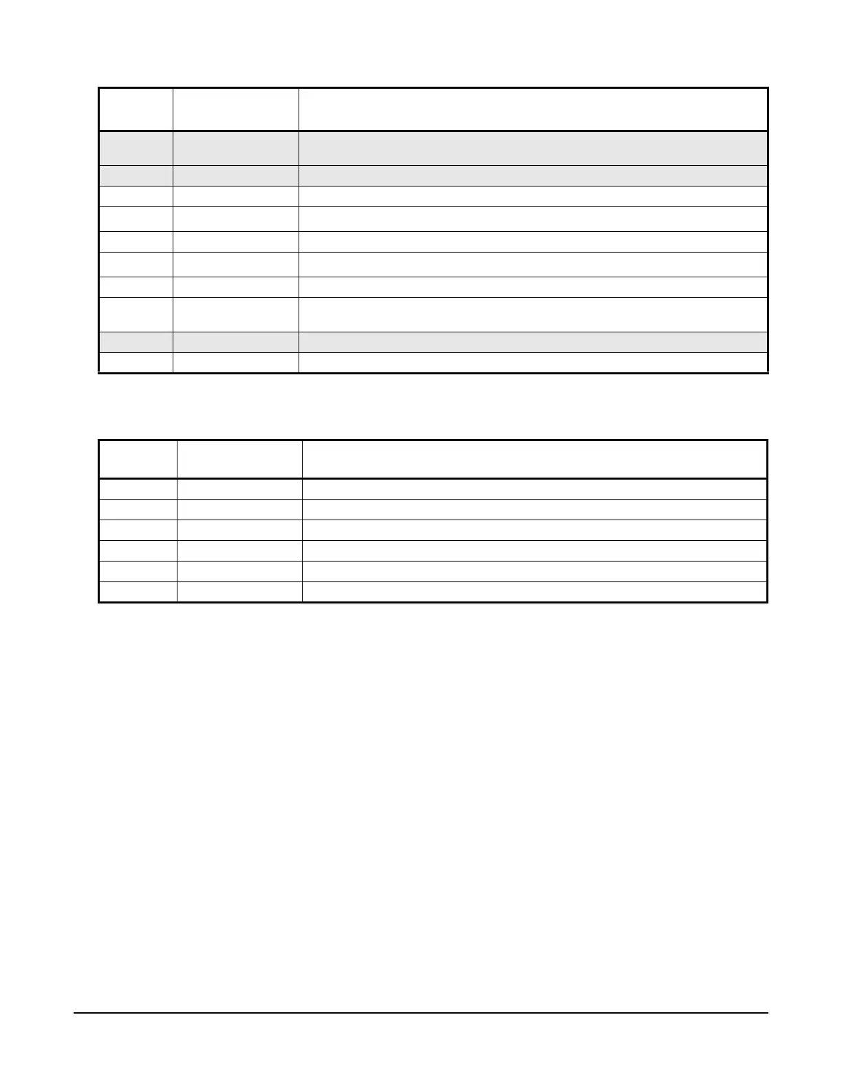
B Relay Output (N.C.) During normal operation, relay contacts B and C are connected (maximum alarm
load: 230 VAC, 0.3 A or 30 VDC, 0.3 A).
C Relay Output (C) Relay output common
10 +5 V +5 VDC Supply for P499R Transducers (15 mA maximum)
2 Analog Input
Analog Input 1 (AI1) accepts 0
–5 V or 0–10 V DC analog input signals
5 Analog Common Common for analog inputs
4 Analog Input
Analog Input 2 (AI2) accepts 4
–20 mA analog input signals
SD Common Common for contact inputs (when using Sink logic - default setting).
STF Contact Input Forward rotation. Must connect STF to SD terminal (common) using the
factory-supplied jumper to allow the VFD to rotate in a forward direction.
STR Contact Input Reverse rotation (not used)
SD Common Common for contact inputs (when using Sink logic - default setting).
1. Gray cells indicate a terminal that is typically not used in condenser fan speed control applications.
Table 12: VFD68Dxx Drives Low-Voltage Connection Information for the High Input Signal
Select Board
Terminal
Label
Signal Type Description
5V +5V +5 VDC Supply for P499R Transducers (15 mA maximum)
IN1 Analog Input Analog Input 1 for 0.5 to 4.5 V Ratiometric High Signal Select
GND Analog Common Common for analog inputs
5V +5V +5 VDC Supply for P499R Transducers (15 mA maximum)
IN2 Analog Input Analog Input 2 for 0.5 to 4.5 V Ratiometric High Signal Select
GND Analog Common Common for analog inputs
Table 11: VFD68Dxx Drives Low-Voltage Connection Information for the Primary Board (Part 2 of 2)
Terminal
Label
1
Signal Type Description