Table 63: 5 ton heating charging chart for XA(F,H)*60J and JH(E,V)T*60J in downflow and horizontal right
Ambient
temperature
(°F)
60 47 40 30 17 10 0
CFM
Indoor
temperature
(°F)
60 70 80 60 70 80 60 70 80 60 70 80 60 70 80 60 70 80 60 70 80
1500 Liquid pressure
(subcool)
332
(15)
374
(15)
414
(15)
310
(19)
354
(21)
401
(23)
302
(25)
346
(26)
390
(27)
288
(32)
332
(32)
377
(33)
270
(29)
313
(30)
356
(31)
258
(30)
300
(30)
341
(31)
242
(25)
284
(29)
326
(32)
1750 Liquid pressure
(subcool)
312
(14)
353
(14)
393
(14)
293
(19)
335
(20)
382
(21)
286
(23)
330
(25)
374
(26)
274
(29)
317
(30)
361
(31)
264
(29)
304
(29)
348
(30)
253
(29)
295
(30)
335
(31)
239
(26)
280
(29)
322
(31)
2000 Liquid pressure
(subcool)
293
(14)
332
(14)
373
(13)
275
(18)
319
(19)
363
(20)
269
(22)
314
(24)
359
(26)
259
(26)
302
(27)
344
(30)
254
(26)
295
(26)
336
(27)
245
(26)
286
(27)
326
(28)
234
(25)
273
(26)
313
(28)
- Suction pressure 126 127 128 103 103 104 91 91 91 73 74 75 50 51 52 42 43 44 34 34 35
Electrical connections
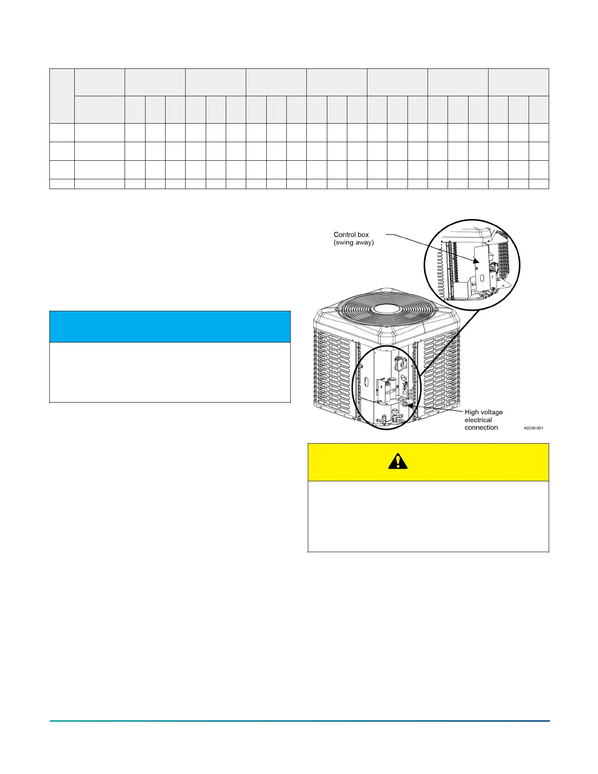
General information and grounding
The control box cover is held in place with three screws,
one screw in each lower corner and one screw at the top
center post. The control box can swing open by removing
the screw from the center of each side of the control box
and allowing the control box to lower an inch or so into a
pivotal position.
NOTICE
Flexible electrical wiring must be installed in order to
use the swing away function of the control box. Rigid
type electrical connections require the wiring to be
disconnected in order to swing the control box open.
The control box can then swing open from the left by
rotating on the right side pivots for easy service of
refrigeration components. If no wiring is in or routed
through the control box, it can be removed from the
unit by lifting slightly, tilting the top hinge out, and
lifting the bottom hinge out. During the installation, it
is recommended to route the low voltage wiring for the
thermostat along the unit high voltage wiring to help
facilitate the swing away feature of the control box. See
Figure 9.
Check the electrical supply to be sure that it meets the
values specified on the unit nameplate and wiring label.
Power wiring, control (low voltage) wiring, disconnect
switches and over current protection must be supplied
by the installer. Wire size must be sized per NEC
requirements.
Figure 9: Outdoor unit swing away control box
CAUTION
All field wiring must use copper conductors only and
be in accordance with Local, National, Fire, Safety
and Electrical Codes. This unit must be grounded with
a separate ground wire in accordance with the above
codes.
The complete connection diagram and schematic wiring
label is located on the inside surface of the unit service
access panel.
Field connections power wiring
1. Install the correct size weatherproof disconnect
switch outdoors and within sight of the unit.
2. Remove the screws at the top and sides of the
corner cover. Slide the control box cover down and
remove from unit.
3. Run power wiring from the disconnect switch to the
unit.
Installation Manual: R-410A Outdoor Split-System Heat Pump - YH2F, THF2, RHP150 Series 31
Johnson Controls Ducted Systems

 Loading...


