11. Release the refrigerant charge into the system.
Open the liquid line service valve first. When the
system pressures have equalized, open the vapor
line service valve by removing the valve caps and
turning the valve counterclockwise using a hex
head wrench. If the service valve is a ball valve,
use an adjustable end wrench to turn the valve
stem one-quarter turn counterclockwise to open.
Do not overturn or the valve stem may break or
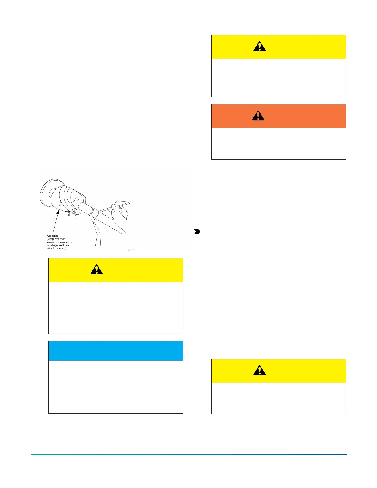
become damaged. See Precautions during brazing
of service valve.
12. Replace the service valve cap finger tight, then
tighten an additional 1/12 turn (1/2 hex flat). The
cap must be replaced to prevent leaks.
13. See System charge for checking and recording
system charge.
Figure 5: Heat protection
CAUTION
Do not install any coil in a furnace which is to
be operated during the heating season without
attaching the refrigerant lines to the coil. The
coil is under pressure which must be released
to prevent excessive pressure build-up and
possible coil damage.
NOTICE
Line set and indoor coil can be pressurized to
250 psig with dry nitrogen and leak tested with
a bubble type leak detector. Then release the
nitrogen charge.
Do not use the system refrigerant in the
outdoor unit to purge or leak test.
CAUTION
Do not connect manifold gauges unless
trouble is suspected. Approximately 3/4 oz of
refrigerant will be lost each time a standard
manifold gauge is connected.
WARNING
Never attempt to repair any brazed
connections while the system is under
pressure. Personal injury could result.
Indoor expansion device
Installing the thermostatic expansion
valve (TXV)
About this task:
The following are the basic steps for installation. For
detailed instructions, refer to the Installation Manual
accompanying the TXV kit. Install TXV kit as follows:
Important: Refer to the Technical Guide for the
unit to determine the correct TXV kit to use on this
product.
1. Relieve the holding charge by depressing the
Schrader core on the suction manifold stub out.
2. After the holding charge is completely discharged,
loosen and remove the Schrader core.
3. Place a backup wrench on the distributor, then
loosen and remove the brass distributor nut. Retain
the brass nut for use on the liquid line. Keep the
PTFE washer in place and discard the clear disk.
4. Install the TXV to the distributor assembly with the
supplied fittings. Ensure that the PTFE washer is
seated in the distributor. Hand tighten and turn an
additional quarter turn to seal. Do not over-tighten
fittings. See Figure 6.
CAUTION
Do not over-torque. Do not use slip joint pliers.
This will distort the aluminum distributor and
the brass fitting (potentially causing leaks).
Installation Manual: R-410A Outdoor Split-System Heat Pump - YH2F, THF2, RHP150 Series 11
Johnson Controls Ducted Systems

 Loading...


