5. Slide the nut removed in Step 3 over the supplied
liquid line. Place the supplied PTFE washer from
the TXV kit on the TXV, and install liquid line to the
top of the TXV. Adjust assembly so liquid line aligns
with hole in access panel. Hand tighten the liquid
line, and apply an additional quarter turn to seal.
WARNING
Schrader valve core must not be installed with
TXV installation. Poor system performance or
system failure could result.
Figure 6: TXV installation
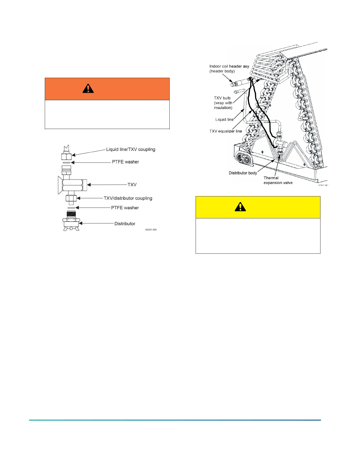
6. Install the TXV equalizer line onto the vapor line by
hand tightening the 1/4 in. SAE coupling nut to the
equalizer fitting, and applying an additional third
turn to seal. See Figure 7.
Figure 7: TXV bulb and equalizer line installations
CAUTION
In all cases, mount the TXV bulb after vapor
line is brazed and has had sufficient time to
cool. Failure to use suction line grommet may
result in premature TXV failure.
7. If the indoor coil is an A coil, skip to Step 8. If not,
pass the TXV temperature sensing bulb through
the suction line split grommet in the access panel.
8. Install the TXV bulb to the vapor line using the bulb
clamps furnished with the TXV assembly. Ensure
the bulb is making maximum contact. See Figure 7
and Figure 8.
a. If possible, install the temperature bulb on a
horizontal run of the vapor line. Ensure that
the bulb is installed at a 10 o’clock or 2 o’clock
position. See Figure 8.
b. If bulb installation is made on a vertical run,
ensure that the bulb is a minimum of 8 in. (20.3
cm) away from the elbow coming out of the
coil. Position the bulb with the tail of the bulb
at the top, so that the bulb acts as a reservoir.
c. Insulate the bulb using thermal insulation
provided to protect it from the effect of the
surrounding ambient temperature. Cover
completely to insulate.
9. After line set is installed, leak test the system.
Installation Manual: R-410A Outdoor Split-System Heat Pump - YH2F, THF2, RHP150 Series12
Johnson Controls Ducted Systems

 Loading...


