CCS Smart Equipment Control Board for Single Packaged Unit (SPU) Controller Installation Instructions 3
Control Board and Wiring Diagrams
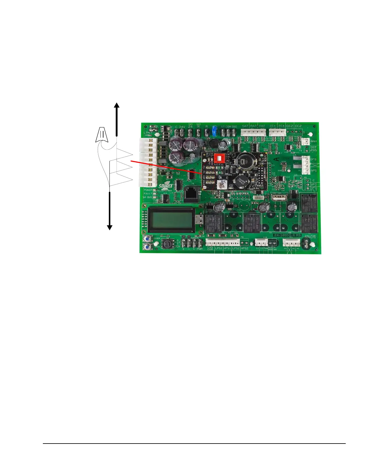
Figure 3 shows the location of the communication
cable terminations on the SPU controller board.
Figure 4 shows the VAV SPU controller communication
riser. .
Figure 3: VAV SPU Control Board Communication Terminations
Communication Cable to
Next VAV box*
Communication Cable to
Next VAV box, Zone
Dampers, and Bypass
Damper
* Move the 4-position terminal block from the Thermostat inputs
to the FC Bus connection of the communications card.
 Loading...