T6634-TE21/22 LCD Digital Fan Coil Thermostat (Modulating/Floating) - Installation Instructions
T6634-TE21/22 液晶数字式风机盘管温控器 (调节型/浮点型) -安装说明
601V-B02A-NC Rev 4-Issue Date 11 2012
2
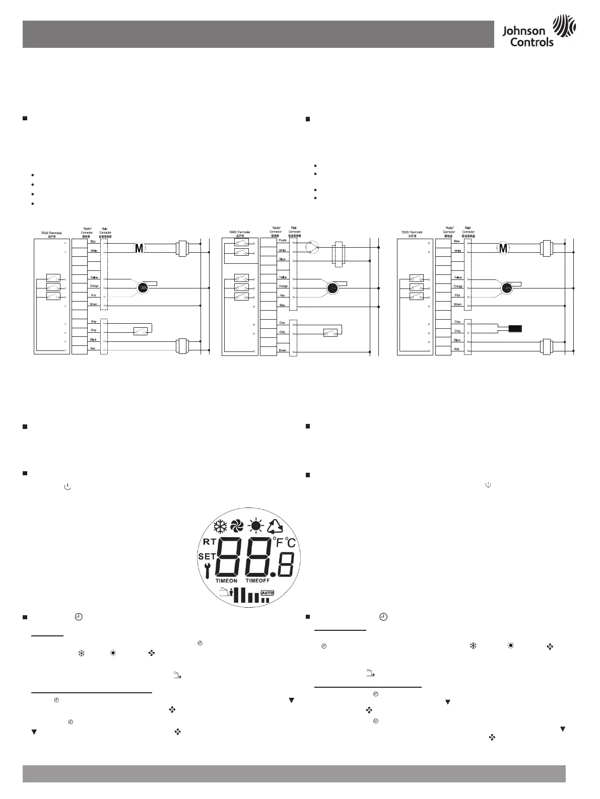
图
4
:
T6634-TE21-9JS0接线图
Figure
4
:
Wiring Diagram for T6634-TE21-9JS0
Wallbox Mounting
To mount the T6000 Series Thermostat:
Pull the external field wiring from the wall through the rectangular opening in the base.
Fasten the base to the wallbox using the appropriate two holes and two Mx5 screws, as
shown in
Figure
2
.
Proceed to the Wiring section for the correct configuration for the applications and units.
Wiring
Wire the unit according to the instructions for the appropriate model.
Note:
When wiring the T6000 Series Digital Fan Coil Thermostat, use wire nuts to finish and
isolate each connection.
When the wiring is completed:
Push the connected wiring through the rectangular hole in the base into the wallbox space.
Hook the thermostat to the hinge at the bottom of the base and gently slide the thermostat
down into position on the mounting base.
Tighten the retention screw.
Proceed to the Setup and Adjustment section to establish the desired settings.
Wiring terminal designations and connections for typical applications appear in
Figure
4
-
6
.
墙装盒安装
安装T6000系列温控器:
把外部接线从墙里拉出并通过打开的方形底座。
通过两个安装孔与两枚Mx5螺钉,把底座固定在安装盒上,如
图2
所示。
根据应用产品的要求进行正确的接线。
接线
根据指导,给适当型号的温控器接线。
注意:
给T6000系列数字式风机盘管温控器接线时,使用接线螺帽完成和绝缘每个接
线端。
当接线完成后
:
通过底座方形孔,把连接线推入墙装盒里。
在底座咬合处把温控器钩住并轻轻推动温控器至安装底座上面。
固定松紧螺丝。
按设定调节键设定想要的参数。
根据
图4
-
6
的典型应用,给指定接线端接线。
图
7
:
T6000 LCD显示
Figure
7
:
T6000 LCD Display Pattern
检查步骤
温控器安装完毕,在离开之前要检查制冷和制热完整的操作循环。这样可以确保所
有控制设备功能正常。如果接线正确,而设备又不能正常工作,请就近联系Johnson
Controls
®
办事处来替换温控器。
设置和调节
按On/Off ( ) 按钮,开启关闭T6000温控器。T6000温控器开机以后,温控器显示环
境温度。LCD显示图标,(如
图7
)。
参考表2,T6000系列温控器出厂设定值
Check-Out Procedure
After the installation, observe the complete operation cycles for cooling and heating control.
This is to make sure that all control devices are functioning correctly. If the device is not
working properly and the wiring is correct, the thermostat should be replaced by contacting
your nearest Johnson Controls
®
Representative.
Setup and Adjustments
Turn ON/OFF the T6000 Thermostat by pressing the On/Off ( ) button. After turning On
the T6000 Thermostat, ambient temperature will be displayed. LCD displays the icons. (see
Figure
7
).
The T6000 Series Thermostat comes with the default settings specified in Table 2.
操作
- M/
按钮
模式操作
T6634-TE21/22温控器, 有三种模式选择如表 1。 按
M
/ 按钮操作温控器,屏幕上会按
顺序出现制冷 (
), 制热 ( ), 仅风机 ( )。5秒后表示该模式已被选定。选好的图标将
显示在液晶屏上(如图6和表1)。
如安装了有人/无人监控装置,有人/无人模式 (
) 将会启动。
时间功能开启和时间功能关闭操作
按下
M
/ 键3秒进入定时开机功能设置。此时
TIMEON
图标出现,并闪烁,使用▲和
键设定定时开机时间(0~24小时范围),按 键进行确认。
再次按下
M
/
键进入定时关机模式设定,此时
TIMEOFF
图标出现,并闪烁,使用▲和
键设定定时关机时间(0~24小时范围),按 键进行确认。
注意
:
如果在3-5秒内没有输入,温控器将回到缺省设置状态。
Operation - M/ Button
Mode Operation
On the T6634-TE21/22, three modes are available as shown in Table 1. Short press of the
M
/
button switches through the sequence of Cooling ( ), Heating ( ), Fan only ( ) modes
followed by operation. The selected icon will flash, the icon is selected after 5 seconds. The
selected icon appears highlighted on the LCD (see Figure 6 and Table 1).
Unoccupied mode (
), will only be activated when the Occupied/Unoccupied contact is wired.
Time-On and Time-Off Operation
Holding down the
M
/ button for 3 seconds will enter the Timer On setting. When the
TIMEON
icon appears and flashes, use ▲ and
keys to set the time duration (0 ~ 24 Hours
Range). Press key
to confirm the settings.
Holding down the
M
/
button for 3 seconds will enter the Timer On setting, additional one
press to enter Time-OFF setting. When
TIMEOFF
icon appears and flashes, use ▲ and
keys to set the time duration (0 ~ 24 Hours Range). Press key
to confirm the settings.
Note:
The thermostat returns to the default screen if no entry occurs within 3-5-seconds.
图5
:
T6634-TE22-9JS0接线图
Figure
5
:
Wiring Diagram for T6634-TE22-9JS0
注:执行器与温控器须使用独立变压器
Note: Separated transformers are required for actuator and thermostat.
LOW
MED
HI
GND
NC
L
TR
NC
GND
C1
C
R
A0
棕色
黄色
橙色
粉红色
白色
蓝色
灰色
灰色
黑色
红色
蓝色
白色
0 10V
~~
低速
中速
高速
Low Speed
Med Speed
High Speed
Unoccupied Volt-Free Contact
无人模式干接点
L
N
24V AC
TR
24V AC
VaL1
VaL2
FC
NC
LOW
MED
HI
GND
C1
NC
L
TR
白色
紫色
黑色
黄色
橙色
粉红色
灰色
灰色
棕色
N
蓝色
关
开
Open
Close
低速
中速
高速
Low Speed
Med Speed
High Speed
Unoccupied Volt-Free Contact
无人模式干接点
L
N
24V AC
接24V阀时,接变压器
Transformer required
for 24Vac actuator
图6
:
T6634-TE21-9JR0接线图
Figure
5
:
Wiring Diagram for T6634-TE21-9JR0
TR
TR
低速
中速
高速
Low Speed
Med Speed
High Speed
粉红色
棕色
L
N
LOW
MED
HI
GND
NC
L
NC
GND
C1
C
R
A0
蓝色
白色
0 10V
外置传感器
24V AC
24V AC
黄色
橙色
白色
蓝色
灰色
灰色
黑色
红色
 Loading...