TEC3000 Series Proportional Fan Coil and Individual Zone Thermostat Controllers with Dehumidification
Capability Installation Instructions
11
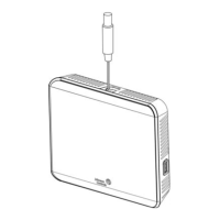
Note: VAV and 2-pipe systems should connect their valve to the heating output.
Figure 11: Floating Control Two-Pipe Heating and Cooling Hydronic Valve Control Fan Coil Application
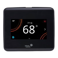
Figure 12: Floating Control Two-Pipe Heating and Cooling Hydronic Valve Control with Changeover Fan
Coil Application
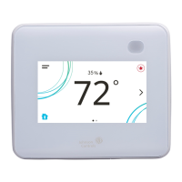
Figure 13: Proportional 0 to 10 VDC Control
(Two-Pipe and Four-Pipe Fan Coil Applications)
Figure 14: AUX Contact Wiring
FIG:model_2_htng_clng_hdrnc
Room Temperature
Control Thermostat
FIG:model_2_htng_clng_hdrnc_chngvr
Proportional
Heating/Cooling
Valve
Optional Water
Supply Sensor
Room Temperature
Control Thermostat
Supply Water
Temperature Sensor
Two-Pipe Applications
Four-Pipe Applications
FIG:model_2_proportional
Heating/Cooling
Valve
Cooling
Valve
Heating
Valve
COM
24V
HTG
AUX Contact
FIG:Aux Contact Wiring
Load
Hot
19 to 30 VAC

 Loading...