PB_VA-748x_12 2012
4
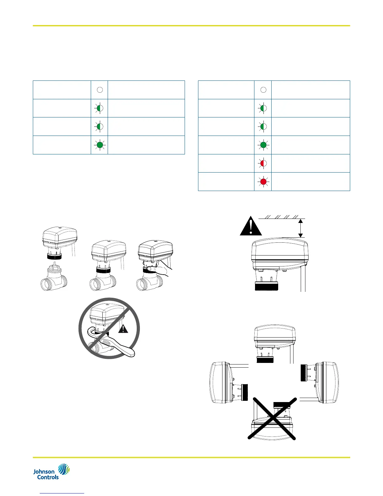
Operating■status■indication
24Vac/ 230Vac Floating Model
The floating models are equipped with a green LED
which provides the information about the operating status
as follow:
OFF No■power■supply
GREEN■BLINKING
Moving■to■position
GREEN■BLINKING
End■stroke■confirmation
GREEN■STEADY■ON
End■Stroke■reached
24Vac/Vdc Proportional Model
The proportional models are equipped with a bi-colour
LED (green-red) which provides the information about the
operating status and diagnostic as follow:
OFF No■power■supply
GREEN■BLINKING
Moving■to■position
GREEN■BLINKING
End■stroke■confirmation
GREEN■STEADY■ON
Position■reached
RED■BLINKING
Cycle
RED■STEADY■ON
4/20mA■or■2/10Vdc■signal■lost
Mounting■Instruction
When mounting the actuator on terminal unit valves,
please follows the instruction below:
OK
NO
Never use the actuator as a mounting lever.
• It is recommended that the valves be mounted upright or at
angles not greater than 90° in an easily accessible location.
• Do not mount the actuator upside down to avoid dripping
water, which could enter the housing and damage the
mechanism or motor.
• Do not cover with insulating material.
• Sufficient clearance must be allowed for actuator removal
(refer to the dimension drawings).
>15 cm
• Mounting position: