10
FORM 145.13-NO2
ISSUE DATE: 1/22/2020
SECTION 1 - INSTALLATION
INSTALLATION
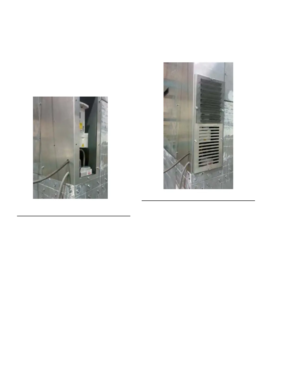
For units utilizing the VAV option, install a field sup-
plied 1/4-inch push-on tube to the return air side of the
unit. Pass the tube through the opening on the side of
the corner post adjacent to the VFD controls, and con-
nect to the negative (LOW) side fitting.
Install a field supplied Pitot tube in the supply duct as
required, run 1/4-inch push-on tube to the corner post
opening, and connect to the positive (HIGH) side fit-
ting.
LD20863
FIGURE 5 - CONNECTING NEGATIVE AND
POSITIVE SIDE FITTINGS
Check that the tubes are secure inside the duct and
firmly connected to transducer fitting. If they are not,
the unit will not operate as intended.
INSTALL GRILLE COVER
When the unit is wired and the push-on tubing is con-
nected to the transducer, attach the grille cover using
the screws provided, with angled blades point upward
at the top.
LD20864
FIGURE 6 - VFD GRILLE COVER