11
FORM 145.13-NO2
ISSUE DATE: 1/22/2020
2
SECTION 2 - OPERATION
INPUT/OUTPUT
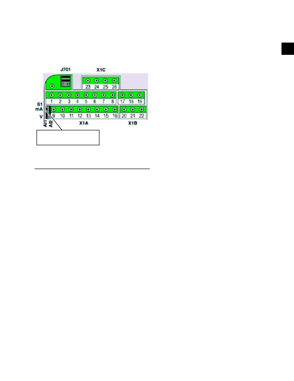
Jumper required between 10, 11
FIGURE 7 - INPUT/OUTPUT DIAGRAM
PARAMETER TABLES
In the parameter menu, set the following parameters
listed in the following parameters tables to operate the
VFD controller correctly. For troubleshooting, check
that the parameters match.
Jumper is set to 0–10VDC for
DSH/DSV C-gen
DISPLAY
In AUTO MODE, the following parameters display on
control display:
1. 30–60Hz is the output frequency to the motor. The
minimum factory set frequency allowed is 30 Hz.
2. 0.0–Nominal Motor Amps. The maximum amps
draw is factory set, and is set to nominal amp
draw of motor used.
3. 0.0–5.0 "WC is the actual reading from the pres-
sure transducer.
4. The setpoint value is displayed in the upper-right
corner. Values range from 0% to 100%. That is
the actual setpoint for the controller. The setpoint
can be 0%, which is 0.0 "WC or 100%, which is
5.0"WC.