VG1000 Series Forged Brass Ball Valves Installation Instructions
9
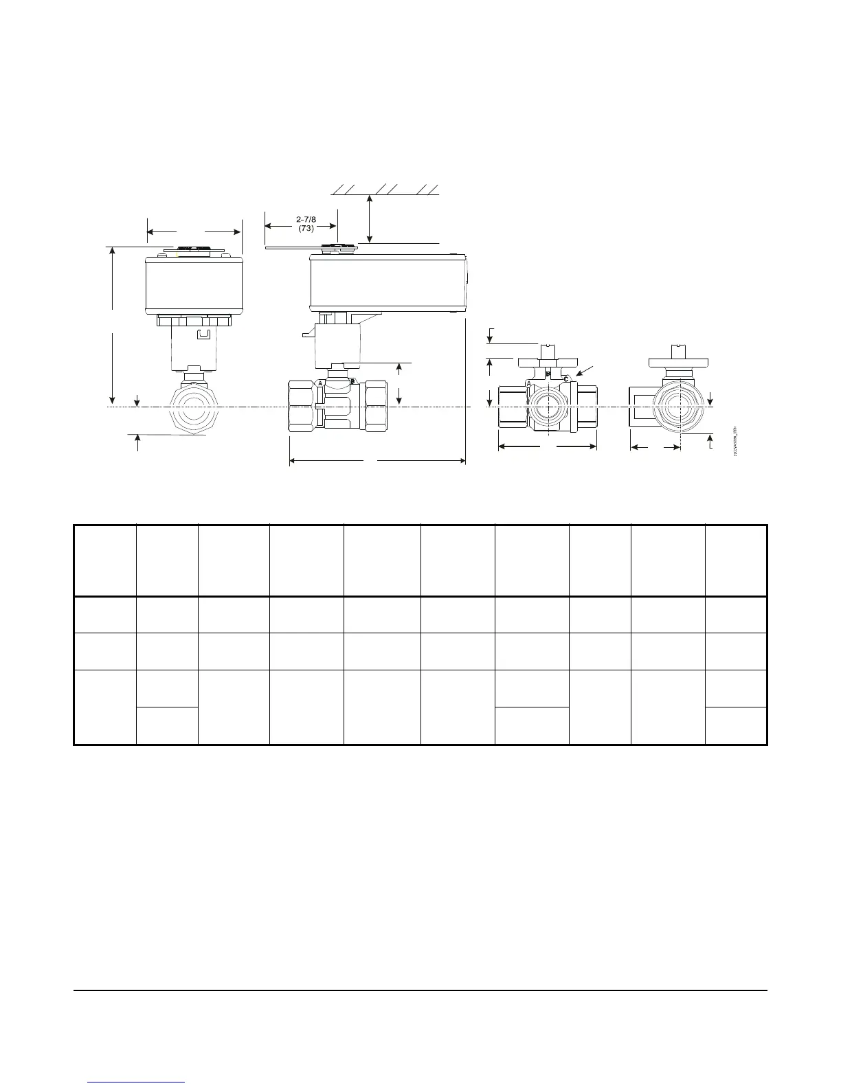
See Figure 10 for dimension drawings of the Spring Return VA9208 Actuated VG1241, VG1245, VG1841, and
VG1845 Series NPT End Connection Ball Valves with M9000-561 Thermal Barrier. See Table 7 for specific model
linkage dimensions.
Table 7: VA9208 Actuated VG1241, VG1245, VG1841, and VG1845 Series Ball Valve with Optional
M9000-561 Thermal Barrier Installed Dimensions, in. (mm)
Valve
Size in.
(DN)
1
1. Port A must always be connected to the coil.
Valve
Style
A
(With
Thermal
Barrier)
A
(Without
Thermal
Barrier)
BCDEFG
1-1/4
(DN32)
All 9-17/64
(235)
7-11/16
(195)
1-1/32
(26)
1-23/32
(44)
7-1/4
(184)
3-15/16
(100)
11/32
(9)
1-31/32
(50)
1-1/2
(DN40)
All 9-15/16
(240)
7-7/8
(200)
1-9/64
(29)
1-57/64
(48)
7-7/16
(189)
4-21/64
(110)
11/32
(9)
2-11/64
(55)
2
(DN50)
2-way 9-31/32
(244)
8-1/32
(204)
1-15/32
(37)
2-1/8
(54)
7-11/16
(195)
4-27/32
(123)
11/32
(9)
N/A
3-way 7-7/8
(200)
2-27/64
(62)
Figure 10: Spring Return VA9208 Actuated VG1241, VG1245, VG1841, and VG1845 Series Ball Valve with
Optional M9000-561 Thermal Barrier Installed Dimensions, in. (mm)
3-29/32
(99)
A
B
3-1/2 (89)
Clearance Required
 Loading...