VG1000 Series Forged Brass Ball Valves Installation Instructions
8
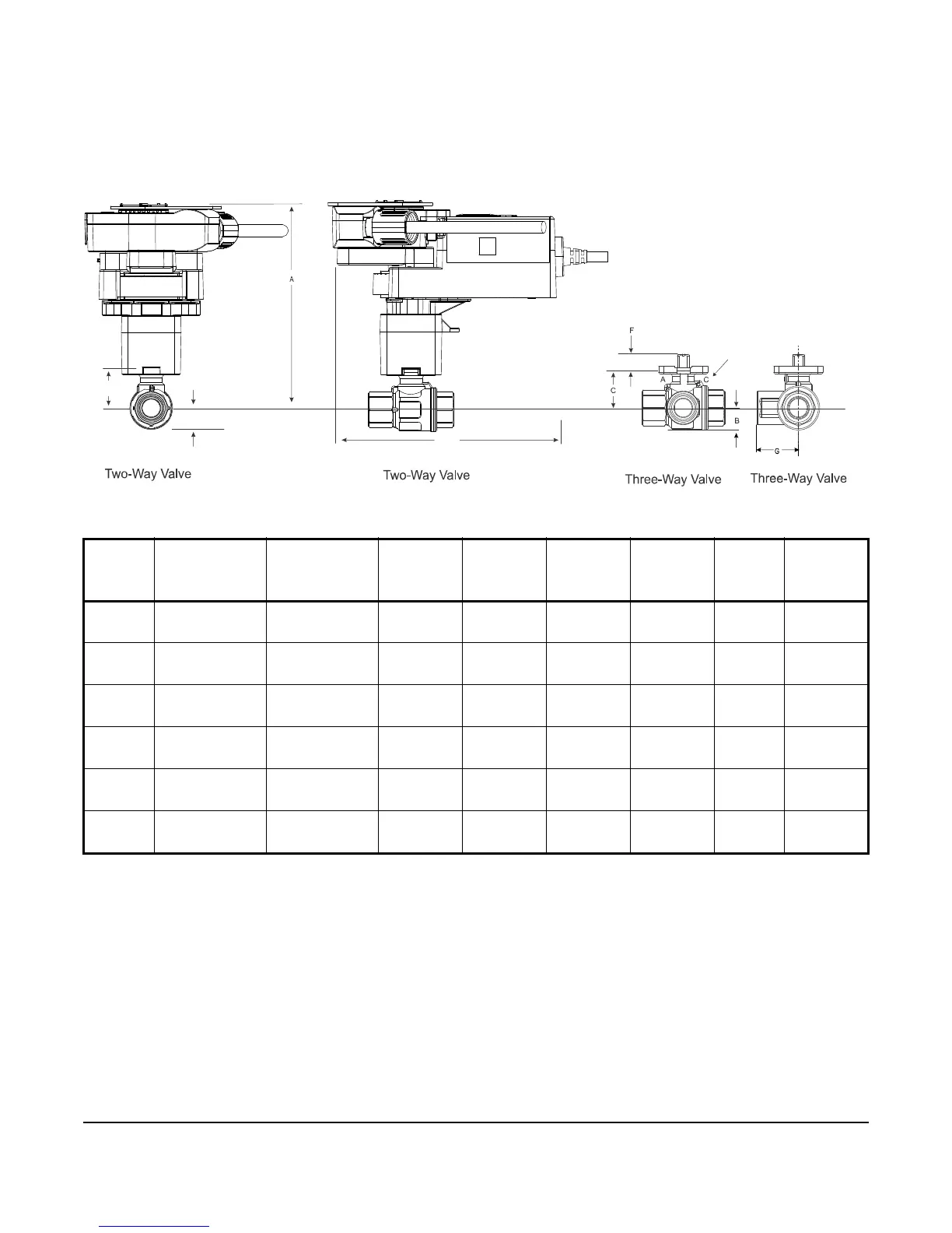
See Figure 9 for dimensions of the Non-Spring Return VA9300 Actuated VG1241, VG1245, VG1841, and VG1845
Series Ball Valve with Optional M9000-561 Thermal Barrier and M9300-2 Switch Kit. See Table 6 for specific model
linkage dimensions.
Table 6: VA9300 Actuated VG1241, VG1245, VG1841, and VG1845 Series Ball Valve with Optional
M9000-561 Thermal Barrier and M9300-2 Switch Kit Dimensions, in. (mm)
Valve
Size, in.
(DN)
A (With
Thermal
Barrier)
A (Without
Thermal
Barrier)
BCDEFG
1/2
(DN15)
6-3/25
(155.7)
4-3/4
(120.7)
21/32
(17)
1-7/32
(31)
6-21/32
(169)
2-33/64
(64)
11/32
(9)
1-1/4
(32)
3/4
(DN20)
6-3/25
(155.7)
4-3/4
(120.7)
21/32
(17)
1-7/32
(31)
6-21/32
(169)
2-51/64
(71)
11/32
(9)
1-13/32
(36)
1
(DN25)
6-1/5
(157.7)
4-21/25
(122.7)
3/4
(19)
1-5/16
(33)
6-21/32
(169)
3-13/32
(87)
11/32
(9)
1-45/64
(43)
1-1/4
(DN32)
6-16/25
(168.7)
5-1/4
(133.7)
1-1/32
(26)
1-23/32
(44)
6-21/32
(169)
3-15/16
(100)
11/32
(9)
1-31/32
(50)
1-1/2
(DN40)
6-4/5
(172.7)
5-3/7
(137.7)
1-1/8
(29)
1-7/8
(48)
6-21/32
(169)
4-21/64
(110)
11/32
(9)
2-11/64
(55)
2
(DN50)
6
(177.2)
5-5/8
(142.7)
1-15/32
(37)
2-1/16
(53)
6-21/32
(169)
4-27/32
(123)
11/32
(9)
2-27/64
(62)
Figure 9: Non-Spring Return VA9300 Actuated VG1241, VG1245, VG1841, and VG1845 Series Ball
Valve with Optional M9000-561 Thermal Barrier and M9300-2 Switch Kit Dimensions, in. (mm)
FIG:Thermal Barrier
B
Port Marking
 Loading...