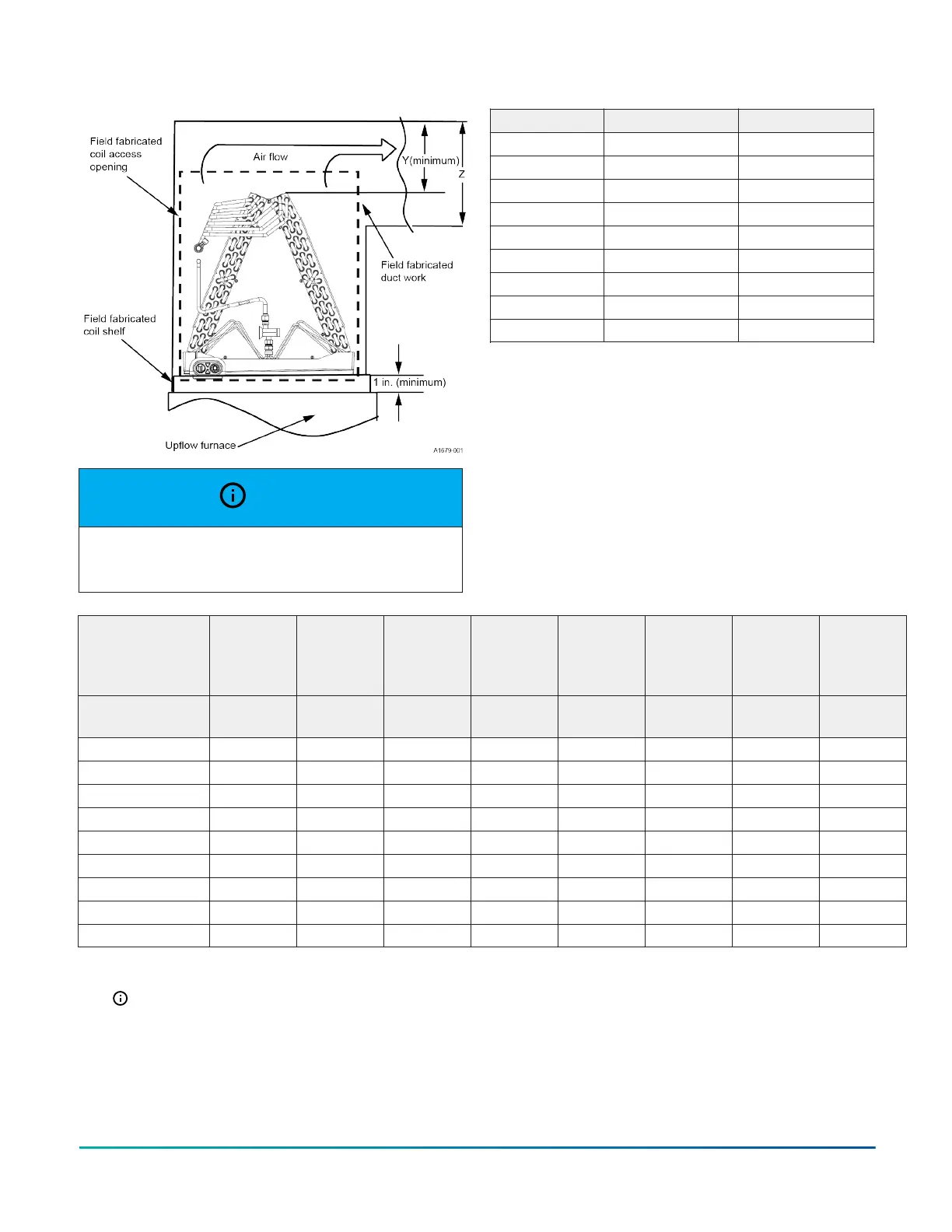
Figure 32: Upflow coil installation
NOTICE
Dimension Y must be at least 2/3 of dimension Z. See
Figure 32.
Table 6: Coil projection dimensions - XAU coils
Coil size Dimension Y (in.) Dimension Z (in.)
XAUA18A 3 1/2 5 1/4
XAUA24B 4 1/2 6 3/4
XAUB30C 4 1/2 6 3/4
XAUB36D 5 1/2 8 1/4
XAUC42E 6 1/2 9 3/4
XAUC48F 6 1/2 9 3/4
XAUC60G 9 13 1/2
XAUD60G 9 13 1/2
XAUD60H 9 13 1/2
3. Install the plenum on the furnace and secure
with screws through the 1/2-in. flange out on the
plenum.
4. Cut an opening in the front of the supply air
plenum. See Figure 32, Figure 33, Table 6, and Table
7 for coil and coil access dimensions.
5. Using a folding tool and hand seamer, bend the
sides and top edges of the cut opening forward
from the plenum at a 90° angle. See Figure 33.
Table 7: Duct work dimensions (in.) - XAU coils
Cabinet
width
Cabinet
height
Coil shelf
opening
width
pre-form
Panel
height
Duct
connector
lower
Duct
connector
upper
Opening
width
pre-form
Opening
height
pre-form
Coil model A (in.)
B (in.)
(minimum)
C (in.) D (in.) E (in.) F (in.) G (in.) H (in.)
XAUA18A 13 1/2 22 9 1/2 19 19 1/2 13 11 1/2 18
XAUA24B 13 1/2 24 9 1/2 21 21 1/2 13 11 1/2 20
XAUB30C 16 1/2 26 12 1/2 23 23 1/2 16 14 1/2 22
XAUB36D 16 1/2 26 12 1/2 23 23 1/2 16 14 1/2 22
XAUC42E 20 28 16 25 25 1/2 19 1/2 18 24
XAUC48F 20 30 16 27 27 1/2 19 1/2 18 26
XAUC60G 20 34 16 31 31 1/2 19 1/2 18 30
XAUD60G 23 1/2 34 19 1/2 31 31 1/2 23 21 1/2 30
XAUD60H 23 1/2 38 19 1/2 35 35 1/2 23 21 1/2 34
Note: All dimensions are in inches. See Figure 33, Figure 34, and Figure 36.
Installation Manual: XAF, XAH, and XAU Series - Full Cased and Uncased Coils for Cooling and Heat Pumps 23
Johnson Controls Ducted Systems